Rockwell Automation Publication 1756-UM058G-EN-P - November 2012 117
Install ControlLogix I/O Modules Chapter 6
NEMA Clamp
Follow these steps to wire a NEMA clamp.
1. Strip 8 mm (5/16 in.) maximum length of wire.
2. Turn the terminal screw counterclockwise.
3. Insert the stripped end of the wire under the plate on the terminal.
4. Turn the terminal screw clockwise until the wire is secured.
The open section at the bottom of the RTB is called the strain relief area. The
wiring from the connections can be grouped with a plastic tie.
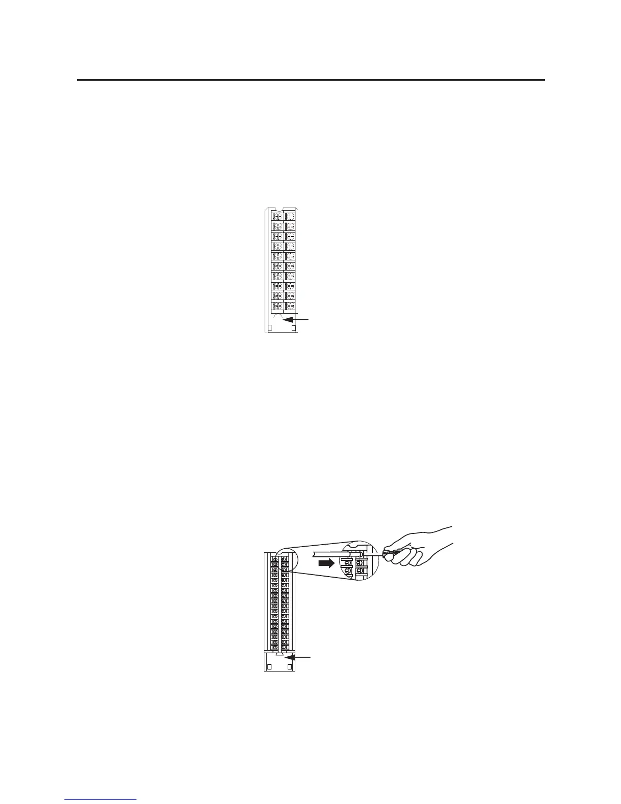
Spring Clamp
Follow these steps to wire a spring clamp.
1. Strip 11 mm (7/16 in.) maximum length of wire.
2. Insert the screwdriver into the outer hole of the RTB to depress the spring-
loaded clamp.
3. Insert the wire into the open terminal and remove the screwdriver.
Strain Relief Area
40201-M
20860-M
Strain Relief Area

 Loading...


