Communication Interface Module
Cat. No. 1784KT/B
Installation Data
7
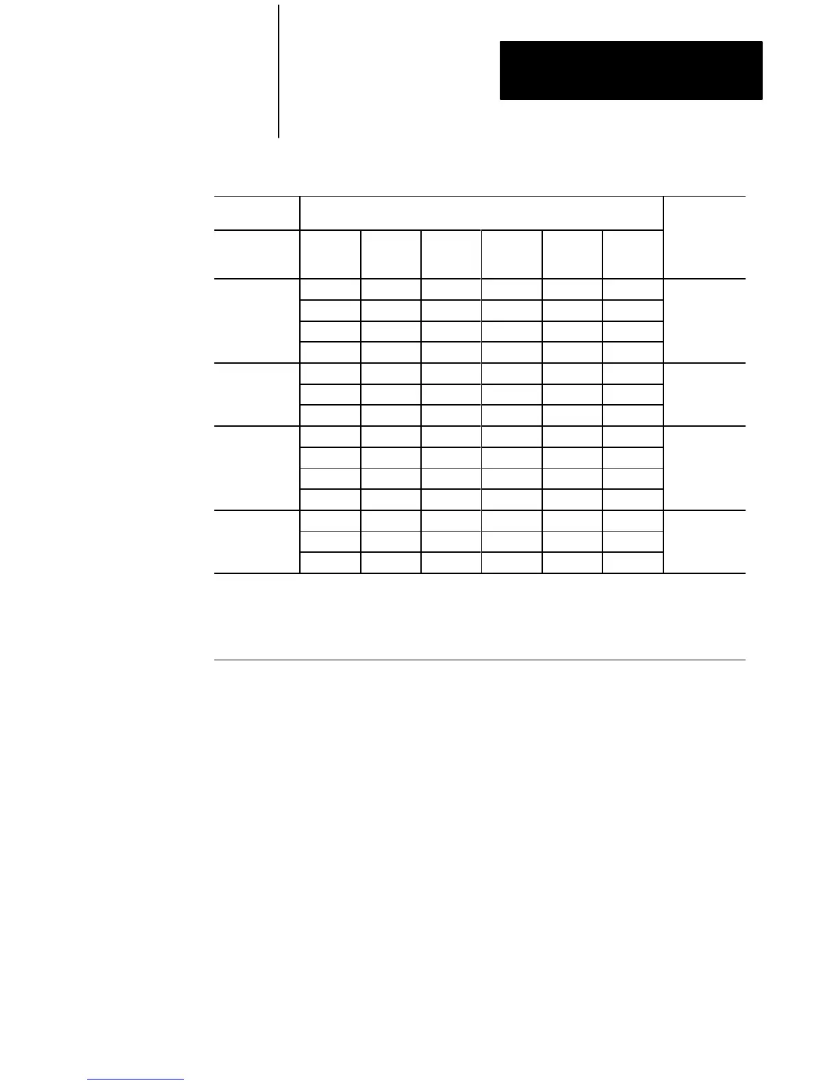
Table B
Selecting
a memory location
Memory
Address (Hex)
PCB Board Switch Settings Switch
Settings
2
M
L
S
S
B
B
A14
(switch 1)
A15
(switch 2)
A16
(switch 3)
A17
(switch 4)
A18
(switch 5)
A19
(switch 6)
LM
SS
BB
A000:0000 up up up down up down 000101
A400:0000 down up up down up down 100101
A800:0000 up down up down up down 010101
AC00:0000 down down up down up down 110101
B000:0000 up up down down up down 001101
B400:0000 down up down down up down 101101
B800:0000 up down down down up down 011101
C000:0000 up up up up down down 000011
C400:0000 down up up up down down 100011
C800:0000 up down up up down down 010011
CC00:0000 down down up up down down 110011
D000:0000 up up down up down down 001011
1
D400:0000 down up down up down down 101011
D800:0000 up down down up down down 011011
1
This is the factoryset address and is the recommended setting. Some system peripherals (such as VGA cards)
may require a different address. Check your system peripheral's documentation to see if it requires different
settings.
2
This is the 6200 software online configuration setting for the 1784KT.
up = 0
down = 1
7. Select an interrupt setting. Your choices are:
- IRQ3
- IRQ4
- IRQ5
- IRQ7
- no interrupt
Table C shows the recommended interrupt settings for Allen-Bradley
industrial terminals, workstations and computers that use
the 1784-KT.
 Loading...


