2–6
How to Install Your Analog Module
Publication
17946.5.2 - May 1996
To install the mounting plate on a wall or panel:
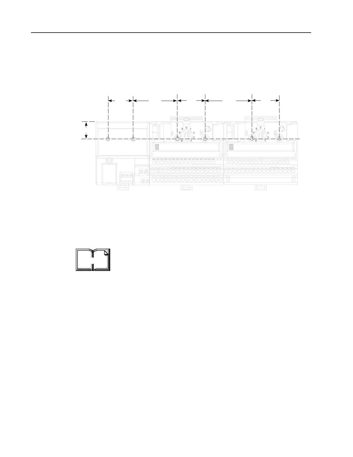
1. Lay out the required points on the wall/panel as shown in the
drilling dimension drawing.
1.4
(35.5)
.83 (21)
2.3
(58.5)
2.3
(58.5)
1.4
(35.5)
1.4
(35.5)
Inches
(Millimeters)
Drilling Dimensions for Panel/Wall Mounting of FLEX I/O
2. Drill the necessary holes for the #6 self-tapping mounting screws.
3. Mount the mounting plate (1) for the adapter module using two
#6 self-tapping screws (18 included for mounting up to 8 modules
and the adapter).
Important: Make certain that the mounting plate is properly
grounded to the panel. Refer to “Industrial Automation
Wiring and Grounding Guidelines,” publication
1770-4.1.
4. Hold the adapter (2) at a slight angle and engage the top of the
mounting plate in the indention on the rear of the adapter module.
5. Press the adapter down flush with the panel until the locking lever
locks.
6. Position the terminal base unit up against the adapter and push the
female bus connector into the adapter.
7. Secure to the wall with two #6 self-tapping screws.
8. Repeat for each remaining terminal base unit.
Note: The adapter is capable of addressing eight modules. Do not
exceed a maximum of eight terminal base units in your system.
More

 Loading...


