3–5
Module Programming
Publication
17946.5.2 - May 1996
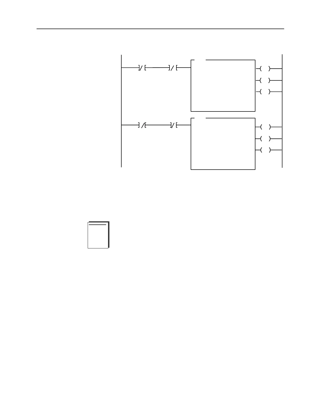
Figure 3.6
PLC5 Family Sample Program Structure for the 1794IE4XOE2
BTR Enable Bit
EN
DN
BTW Enable Bit
1
2
ER
EN
DN
ER
BTR
BLOCK TRANSFER READ
RACK:
GROUP:
MODULE:
DATA FILE:
LENGTH:
CONTINUOUS: N
BTW
BLOCK TRANSFER WRITE
RACK:
GROUP:
MODULE:
LENGTH:
CONTINUOUS: N
2
3
0
N17:0
5
2
3
0
8
Program
Action
CONTROL:
N16:0
DATA FILE:
N17:5
CONTROL:
N16:5
N16:5
15
N16:0
15
Thereafter, the program continuously
performs read block transfers and write block
transfers.
At powerup in RUN mode, or when the
processor is switched from PROG to RUN,
the user program enables a block transfer
read. Then it initiates a block transfer write
to configure the module and send data
values.
BTR Enable Bit
N16:0
15
BTW Enable Bit
N16:5
15
PLC2 Programming
The 1794 analog I/O modules are not recommended for use with
PLC-2 family programmable controllers due to the number of digits
needed for high resolution. In addition, the data returned from the
analog-to-digital converter in the module is 12-bit resolute. This
value is left-justified into a 16-bit field, reserving the most
significant bit for a sign bit. Refer to Appendix B for more
information.

 Loading...


