4–3
Configuring Your Module and Reading Status from Your Module with a Remote I/O Adapter
Publication
17946.5.2 - May 1996
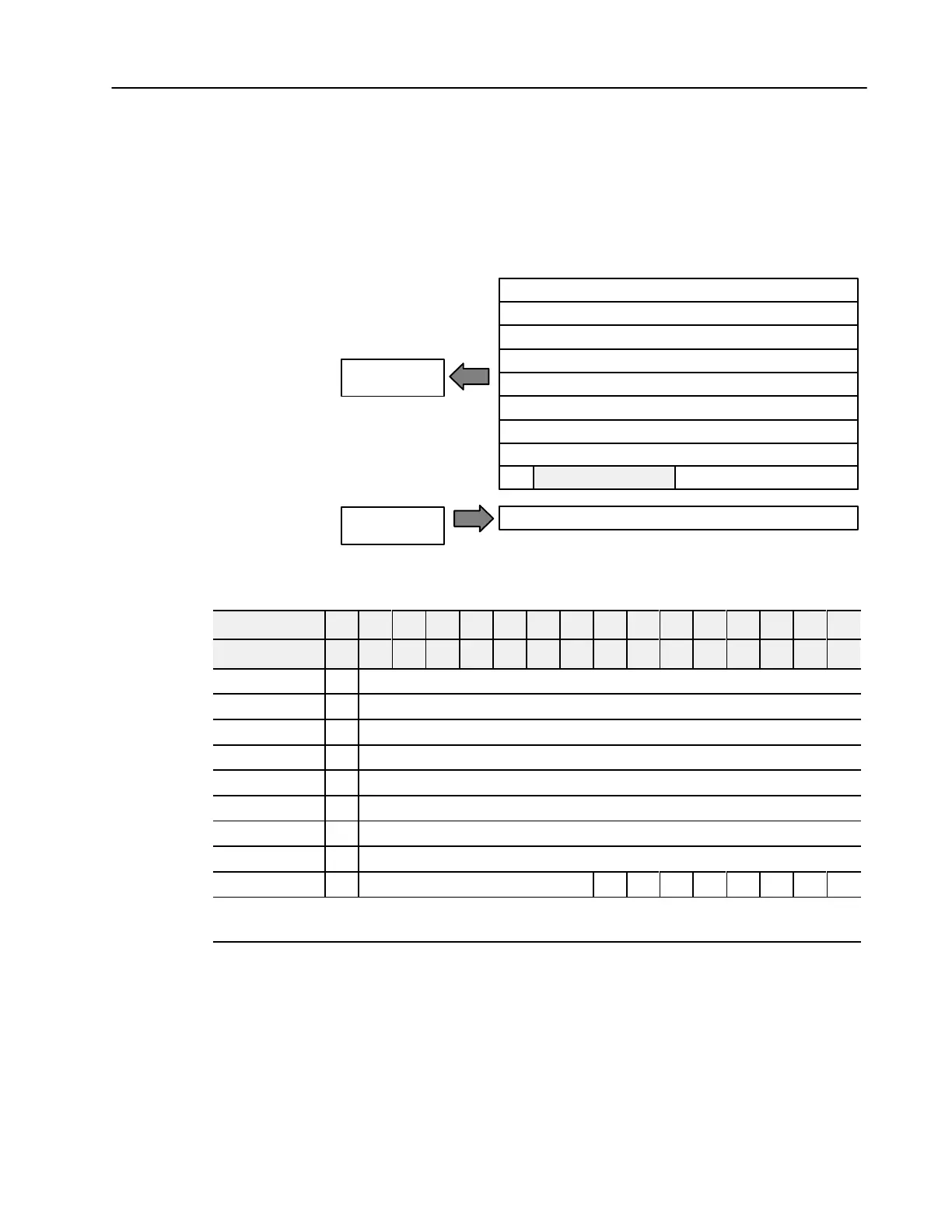
The following read and write words and bit/word descriptions
describe the information written to and read from the analog
modules. Each word is composed of 16 bits.
8 Input Analog Module (Cat. No. 1794IE8 Series B)
Module
Image
I/O Image
Input Data Channel 0
Input Data Channel 1
Input Data Channel 2
Input Data Channel 3
Input Data Channel 4
Input Data Channel 5
Input Data Channel 6
Input Data Channel 7
Underrange
Configure select
Input Size
Output Size
0 or 1 Word
1 to 9 Words
PU
Analog Input Module (1794-IE8) Read
Word/Dec. Bit 15 14 13 12 11 10 09 08 07 06 05 04 03 02 01 00
Word/Octal Bit 17 16 15 14 13 12 11 10 07 06 05 04 03 02 01 00
Read Word 0 S Analog Value Channel 0
Word 1 S Analog Value Channel 1
Word 2 S Analog Value Channel 2
Word 3 S Analog Value Channel 3
Word 4 S Analog Value Channel 4
Word 5 S Analog Value Channel 5
Word 6 S Analog Value Channel 6
Word 7 S Analog Value Channel 7
Word 8 PU Not used - set to zero U7 U6 U5 U4 U3 U2 U1 U0
Where: S
= sign bit (in 2's complement)
U = Underrange bits for 420mA inputs
PU = Power up bit
Mapping Data for the
Analog Modules

 Loading...


