4–5
Configuring Your Module and Reading Status from Your Module with a Remote I/O Adapter
Publication
17946.5.2 - May 1996
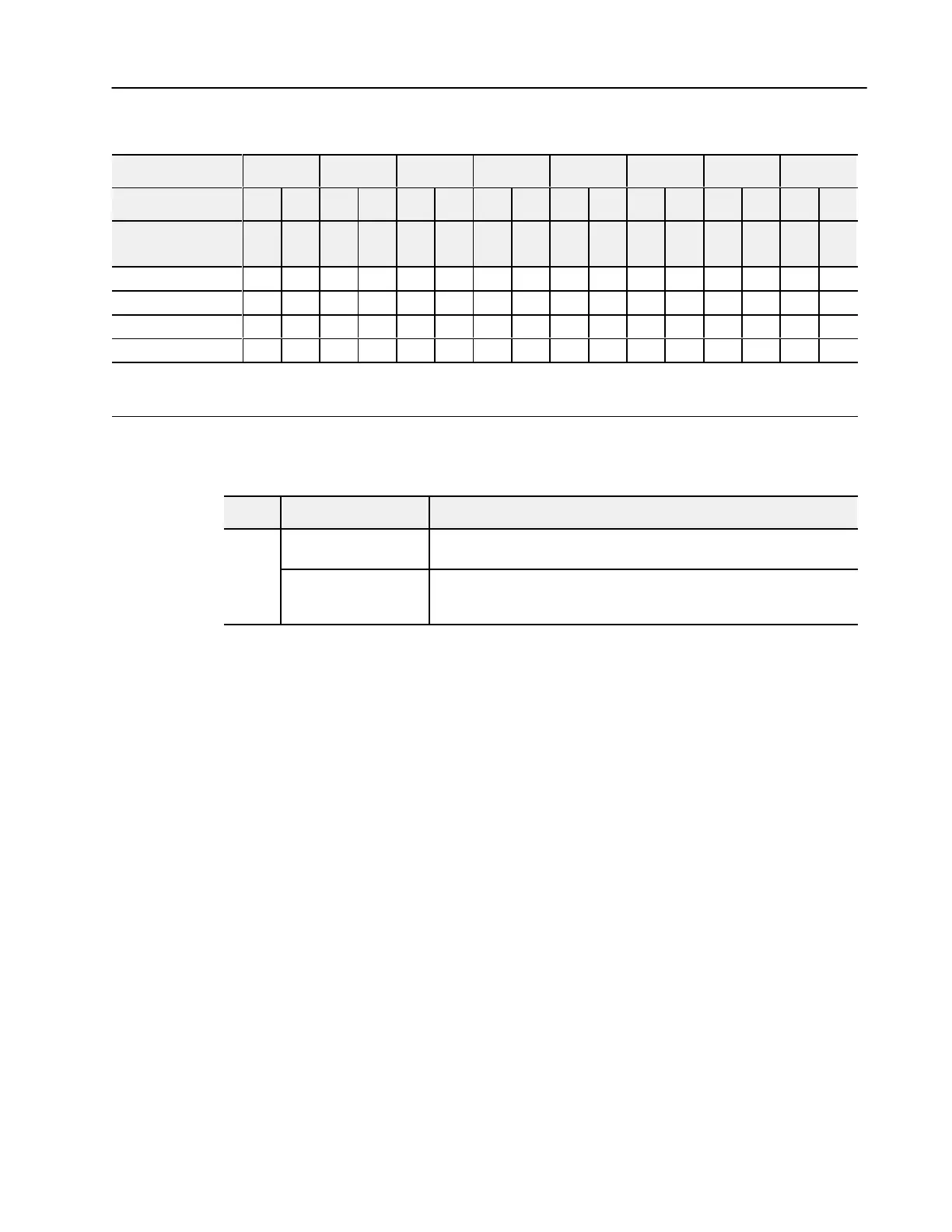
Range Selection Bits for the 1794-IE8/B Analog Input Module
Channel No. Channel 0 Channel 1 Channel 2 Channel 3 Channel 4 Channel 5 Channel 6 Channel 7
F0 C0 F1 C1 F2 C2 F3 C3 F4 C4 F5 C5 F6 C6 F7 C7
Decimal Bits
(Octal Bits)
00
08
(10)
01
09
(11)
02
10
(12)
03
11
(13)
04
12
(14)
05
13
(15)
06
14
(16)
07
15
(17)
0-10V dc/0-20mA 1 0 1 0 1 0 1 0 1 0 1 0 1 0 1 0
4-20mA 0 1 0 1 0 1 0 1 0 1 0 1 0 1 0 1
10 to +10V dc 1 1 1 1 1 1 1 1 1 1 1 1 1 1 1 1
Off
1
0 0 0 0 0 0 0 0 0 0 0 0 0 0 0 0
C
= Configure select bit
F = Full range bit
1
When configured to of
f, individual channels will return 0000H on Series B modules, and 4 to 20mA on Series A modules.
Word/Bit Descriptions for the 1794-IE8/B Analog Input Module
Write
Word Decimal Bit (Octal Bit) Definition
Bits 00-07
Full range bits (F) for individual channels - Bit 00 corresponds to input channel
0, bit 01 corresponds to input channel 1, and so on.
Write
Word 0
Bits 08-15 (1017)
Configure select bits (C) for individual channels - Bit 08 corresponds to input
channel 0, bit 09 corresponds to input channel 1, and so on. Refer to Range Bit
Selections.

 Loading...


