4–10
Writing Configuration to and Reading Status from Your Module with a Remote I/O Adapter
Publication
17946.5.2 - May 1996
Definition
Decimal Bit
(Octal Bit)
Word
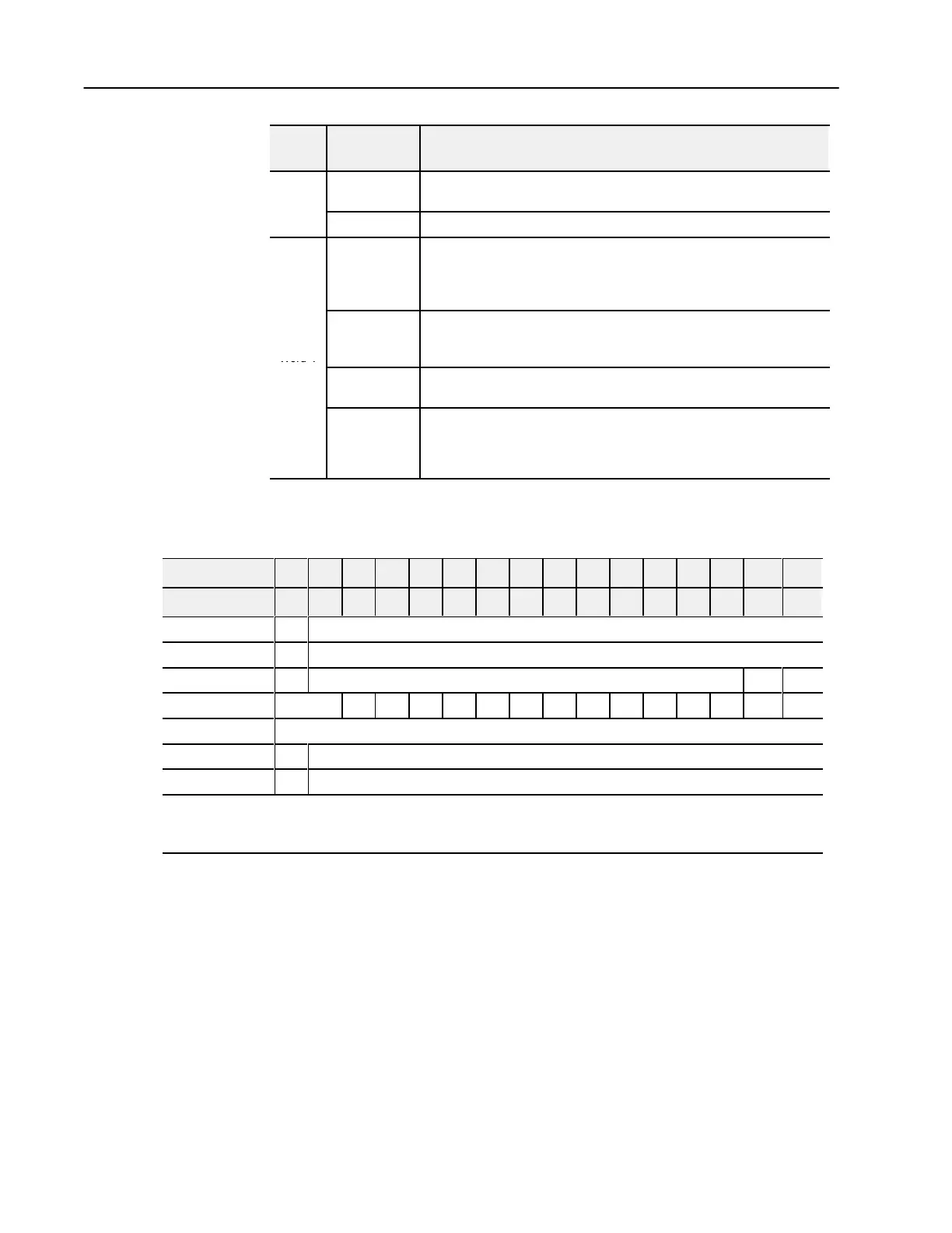
Word 3
Bits 00-14
(00-16)
Channel 3 analog data - 12bit left justified two's complement number;
unused lower bits are zero; 420mA uses all 16 bits.
Bits 15 (17) Channel 3 analog data sign bit.
Bits 00-03
Underrange bits (U) for individual channels (420mA current inputs only) -
Bit 00 corresponds to input channel 0, bit 01 corresponds to input channel 1,
and so on. When set (1), indicates either a broken or open input wire, or input
current is at or below 4mA.
Word 4
Bits 0405
Wire Off bits (W) - Current outputs only - When set (1), the wire on the
current output is broken or the load resistance is too high. Bit 00 corresponds
to channel 0, bit 01 corresponds to channel 2, and so on.
Bits 06-14
(06-16)
Not used
Bit 15 (17)
Power Up bit - included in series B modules only. This bit is always 0 in
series A modules. This bit is set to 1 when all bits in the configuration
register (write word 3) are 0 (unconfigured state). The configuration
register can be cleared by either a reset, or by the user writing all zeroes to it.
Analog Combo Module (1794-IE4XOE2/B) Write Configuration
Block
Word/Dec. Bit 15 14 13 12 11 10 09 08 07 06 05 04 03 02 01 00
Word/Octal Bit 17 16 15 14 13 12 11 10 07 06 05 04 03 02 01 00
Write Word 0 S Analog Data - Output Channel 0
Word 1 S Analog Data - Output Channel 1
Word 2 0 Not used - set to 0 M1 M0
Word 3 Not used C5 C4 C3 C2 C1 C0 0 0 F5 F4 F3 F2 F1 F0
Words 4 and 5 Not used - set to 0
Word 6 S Safe State Value - Output Channel 0
Word 7 S Safe State Value - Output Channel 1
Where: M
= Multiplex control bits
S = Sign bit (in 2's complement)
C = Configure select bit
F = Full range bit

 Loading...


