4–7
Configuring Your Module and Reading Status from Your Module with a Remote I/O Adapter
Publication
17946.5.2 - May 1996
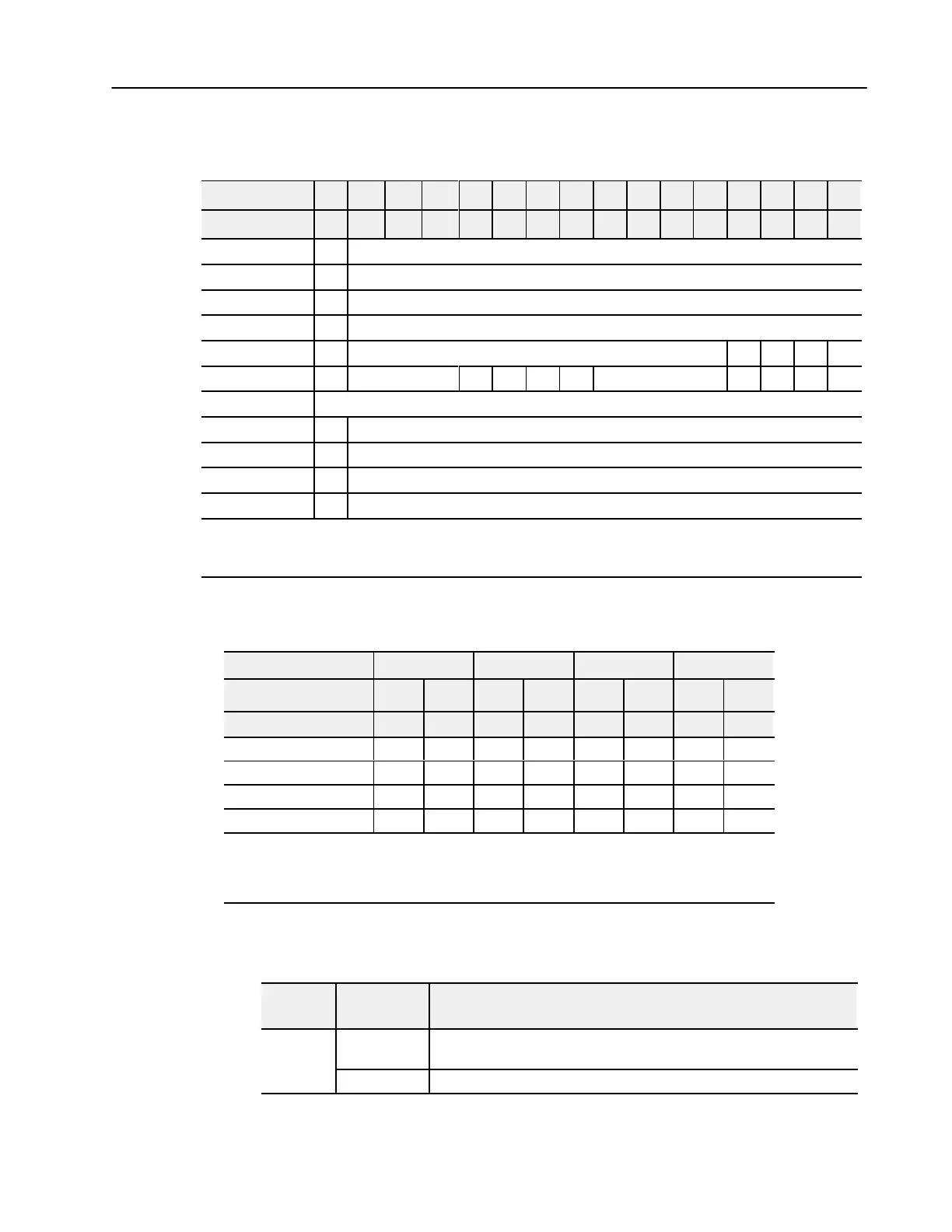
Analog Output Module (1794-OE4/B) Write Configuration
Block
Word/Dec. Bit 15 14 13 12 11 10 09 08 07 06 05 04 03 02 01 00
Word/Octal Bit 17 16 15 14 13 12 11 10 07 06 05 04 03 02 01 00
Write Word 0 S Analog Data - Channel 0
Word 1 S Analog Data - Channel 1
Word 2 S Analog Data - Channel 2
Word 3 S Analog Data - Channel 3
Word 4 0 Not used - set to 0 M3 M2 M1 M0
Word 5 0 Not used - set to 0 C3 C2 C1 C0 Not used - set to 0 F3 F2 F1 F0
Word 6 thru 9 Not used - set to 0
Word 10 S Safe State Value - Channel 0
Word 11 S Safe State Value - Channel 1
Word 12 S Safe State Value - Channel 2
Word 13 S Safe State Value - Channel 3
Where: S
= Sign bit (in 2'
s complement)
M = Multiplex control
C = Configure select bit
F = Full range bit
Range Selection Bits for the 1794-OE4/B Analog Output Module
(Word 5)
Channel No. Channel 0 Channel 1 Channel 2 Channel 3
F0 C0 F1 C1 F2 C2 F3 C3
Decimal Bits (Octal Bits) 00 08 (10) 01 09 (11) 02 10 (12) 03 11 (13)
4-20mA 0 1 0 1 0 1 0 1
0-10V dc/0-20mA 1 0 1 0 1 0 1 0
10 to +10V dc 1 1 1 1 1 1 1 1
Off
1
0 0 0 0 0 0 0 0
C
= Configure select bit
F = Full range bit
1
When configured to of
f, individual channels will send 0V or 0mV on Series B modules. On Series A modules, 2V or 4mA is output
until the module is configured.
Word/Bit Descriptions for the 1794-OE4/B Analog Output
Module Write
Word
Decimal Bit
(Octal Bit)
Definition
Write Word
Bits 00-14
(00-16)
Channel 0 analog data - 12bit left justified two's complement number; unused
lower bits are zero; 420mA uses all 16 bits.
0
Bits 15 (17) Channel 0 analog data sign bit.

 Loading...


