3–2
Module Programming
Publication
17946.5.2 - May 1996
The following sample programs show you how to use your analog
module efficiently when operating with a programmable controller.
These programs show you how to:
• configure the module
• read data from the module
• update the module’s output channels (if used)
These programs illustrate the minimum programming required for
communication to take place.
PLC3 Programming
Block transfer instructions with the PLC-3 processor use one binary
file in a data table section for module location and other related data.
This is the block transfer control file. The block transfer data file
stores data that you want transferred to your module (when
programming a block transfer write) or from your module (when
programming a block transfer read). The address of the block
transfer data files are stored in the block transfer control file.
The same block transfer control file is used for both the read and
write instructions for your module. A different block transfer
control file is required for every module.
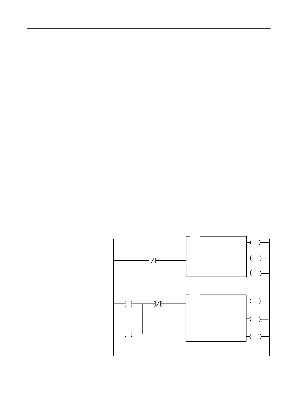
A sample program segment with block transfer instructions is shown
in Figure 3.1, and described below.
Figure 3.1
PLC3 Family Sample Program Structure for a 1794IE8 Module
EN
BTR
BLOCK XFER READ
RACK:
GROUP:
MODULE:
CONTROL:
7
0
0
#B3:0
DATA FILE:
LENGTH:
#B4:0
9
EN
BTW
BLOCK XFER WRITE
RACK:
GROUP:
MODULE:
CONTROL:
7
0
0
#B3:0
DN
DATA FILE:
LENGTH:
#B5:0
1
B3:0
05
Block Transfer
Read Done Bit
ER
Enable
Done
Error
12
15
13
Enable
Done
Error
02
05
03
Block Transfer
W
rite Done Bit
1
2
DN
ER
B3:0
15
Program
Action
At powerup in RUN mode, or when the
processor is switched from PROG to RUN,
the user program enables a block transfer
read. Then it initiates a block transfer write
to configure the module if the powerup bit
is set.
Thereafter, the program continuously
performs read block transfers.
Note: You must create the data file
for the block transfers before you
enter the block transfer instructions.
The pushbutton allows the user to
manually request a block transfer write to
configure the module.
B4:8
15
Pushbutton
Powerup Bit
1
1
Powerup bit included in Series B modules only.
Sample programs for Flex
I/O Analog Modules

 Loading...


