Publication 2098-IN003E-EN-P — April 2004
Ultra3000 Connector Data 2-37
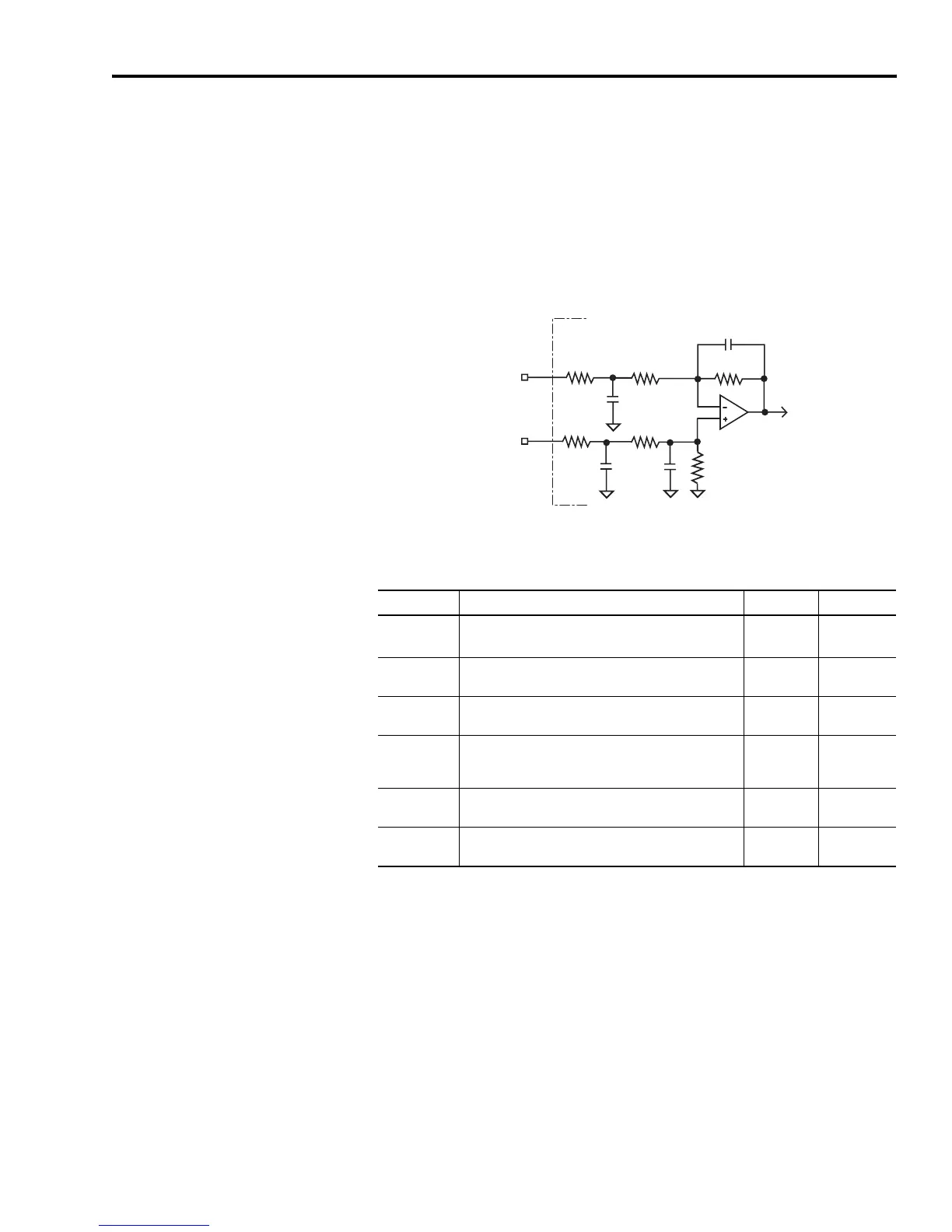
Analog COMMAND Input
The COMMAND input to the drive can provide a position, velocity, or
current command signal. A 14 bit A/D converter digitizes the signal.
The configuration of the input is shown in Figure 2.34.
Figure 2.34
Analog COMMAND Input Configuration
The following table provides a description of the analog COMMAND
input specifications.
10k Ω 10k Ω
20k Ω
20k Ω
1000 pF
1000 pF
0.01
μ
F
COMMAND +
COMMAND -
0.01
μ
F
10k Ω 10k Ω
Ultra3000 Drive
Parameter Description Minimum Maximum
Resolution
Number of states that the input signal is divided into
which is 2
(to the number of bits)
.
14 bits —
Input
Impedance
Open circuit impedance measured between the + and
- inputs.
20 kΩ —
Input Signal
Range
Voltage applied to the input -10V +10V
Offset Error
Deviation from the correct value expected from
analog-to-digital conversion when 0V is applied to the
input.
—50 mV
Gain Error
Deviation of the transfer function from unity gain,
expressed in a percent of full scale.
—1%
Propagation
Delay
Delay from the input to the firmware-accessible
registers.
— 100 μS
 Loading...


