Rockwell Automation Publication 5069-IN003E-EN-P - October 2018 17
Compact 5000 I/O EtherNet/IP Adapters
Connect the Adapter to an EtherNet/IP Network
Use an RJ45 straight cable to connect the adapter to an EtherNet/IP
network.
1. If needed, wire the RJ45 connector as shown.
2. Connect the RJ45 cable to an Ethernet port on the bottom of
the adapter. You can connect two RJ45 cables to the adapter.
Install Compact 5000 I/O Modules
Install Compact 5000 I/O modules on the right side of the adapter.
If the end cap is installed on the adapter, you must remove it before you
can install the I/O modules.
For more information on how to install Compact 5000 I/O modules,
see the installation instructions available with each Compact 5000 I/O
module catalog number.
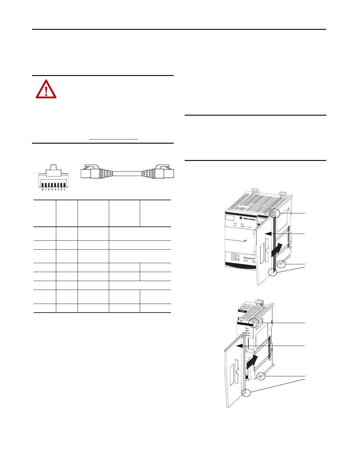
Install the End Cap
A 5069-ECR end cap ships with the adapter.
You must install an end cap on the right side of the last module in a
Compact 5000 I/O system. The end cap covers the exposed
interconnections on the last module in the system. If you do not install
the end cap before powering the system, equipment damage or injury
from electric shock can result.
If the end cap is not installed and you have installed all required
modules in the system, install the end cap.
1. Align the end cap with interlocking pieces on the adapter.
2. Push the end cap toward the DIN rail until it locks into place.
WARNING: If you connect or disconnect the communication
cable with power that is applied to this module or any device on
the network, an electric arc can occur. This arc could cause an
explosion in hazardous location installations.
Be sure that power is removed or the area is nonhazardous
before proceeding.
This warning applies to connections to ports 1 and 2 on both
adapters. For more information on where the ports are on the
adapter, see About the Adapters
on page 5.
Connector
Number
Color
1585J 8-pin
Cables with
Support for 10/
100/1000 Mbps
1585J 8-pin
Cables with
Support for 10/
100 Mbps
1585J 4-pin
Cables with
Support for 10/
100 Mbps
1
White/
Orange
BI_DA+ TxData +
2OrangeBI_DA-TxData -
3
White/
Green
BI_DB+ Recv Data +
4BlueBI_DC+UnusedN/A
5 White/Blue BI_DC- Unused N/A
6 Green BI_DB- Recv Data -
7
White/
Brown
BI_DD+ Unused N/A
8 Brown BI_DD- Unused N/A
IMPORTANT You install the end cap after the last module is installed on
the DIN rail. This design helps to prevent the end cap from
going beyond the locked position.
If you push the end cap beyond the locked position or insert it
from the backwards direction, you can damage the MOD
power bus and SA power bus connector.
ADAPTER
COMPACT 5000
AENTR
5069-AEN2TR
Compact 5000™ I/O
5069-AENTR
Compact 5000™ I/O
Top
Interlocking
Pieces
End Cap
Bottom
Interlocking
Pieces
Top
Interlocking
Pieces
End Cap
Bottom Logix
5000Interlock
ng Pieces
5069-AEN2TR
Adapter
5069-AENTR and
5069-AENTRK
Adapters

 Loading...


