12 1732E ArmorBlock 2 Port Ethernet Module
Publication
1732E-IN004A-EN-E - November 2009
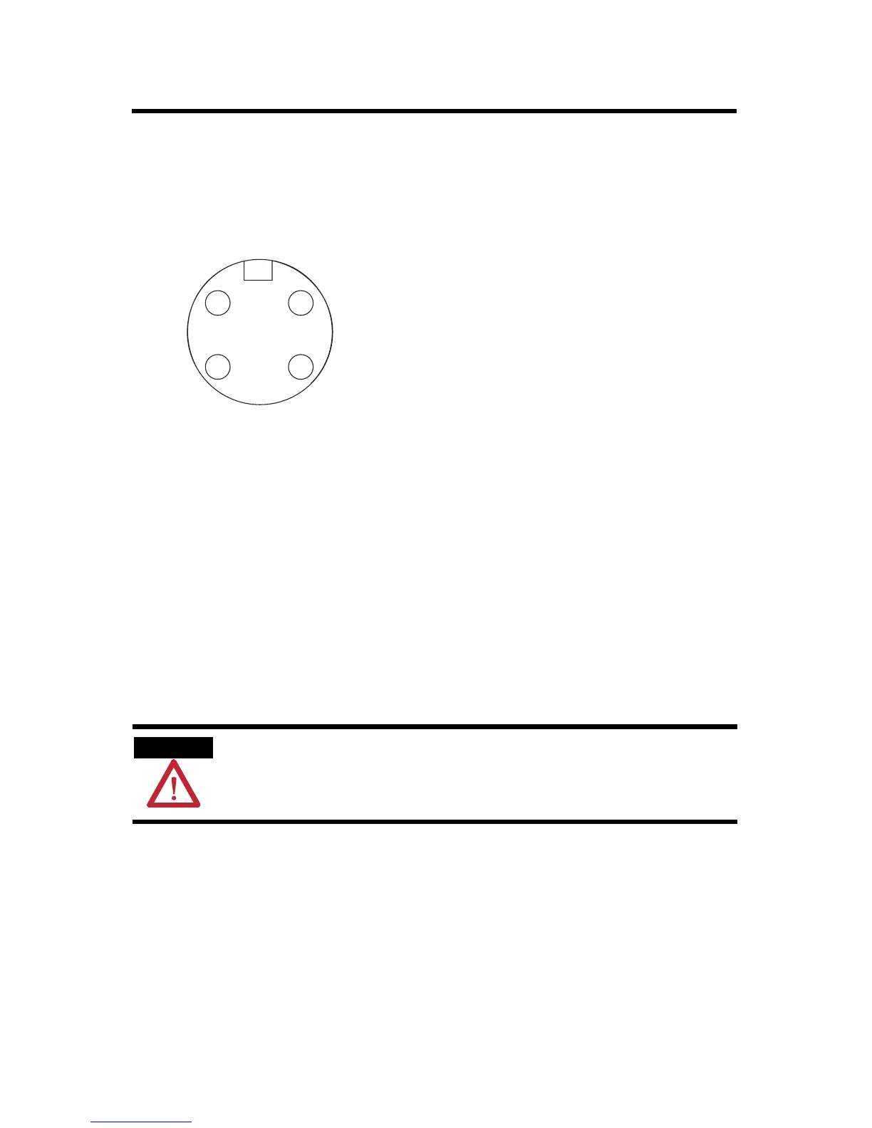
Auxiliary Power Cable
Attach the mini-style 4-pin connector to the mini-style 4-pin receptacle as
shown below.
Auxiliary Power is based on a 4-pin connector system and is used to provide
24V DC power to I/O modules and other devices. Running separate power to
these devices is most typically used for I/O devices with output connections
to prevent power supply interruption due to switching of outputs. However,
some devices require separate auxiliary power to power them regardless of the
presence of outputs.
Depending on the devices used, it may be possible to provide power through
only one pair of the four available pins, and in this case the other available pair
may be used for single channel E-stop through the use of special E-stop drop
or power T-ports and shorting plugs. Allen-Bradley E-stop T-ports and
shorting plugs are red in color for easy identification.
ATTENTION
To comply with the CE Low Voltage Directive (LVD), this equipment and all
connected I/O must be powered from a source compliant with the following:
Safety Extra Low Voltage (SELV) or Protected Extra Low Voltage (PELV).
4 2
3 1
Mini-style 4-Pin Input Male Receptacle
(View into receptacle)
Pin 1 Output power+
Pin 2 Sensor/MDL power+
Pin 3 Sensor/MDL power-
Pin 4 Output power-
44809
 Loading...


