318 Rockwell Automation Publication 1769-UM021G-EN-P - October 2015
Appendix C Connect Power to the Series A L1 CompactLogix 5370 Controllers
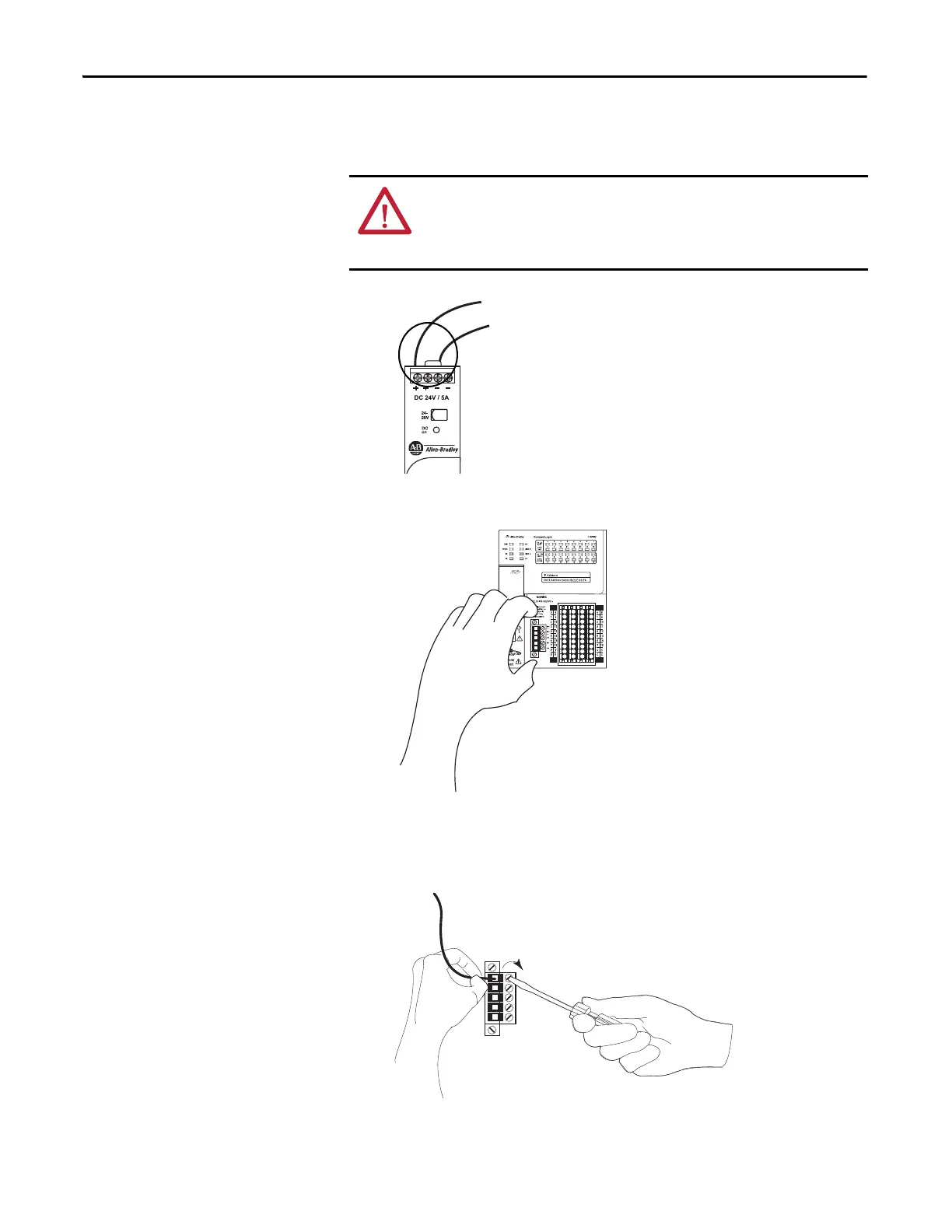
3. Connect wires to the 24V DC+ and 24V DC- connections on the external
24V DC power source.
4. Pull the removable connector off the CompactLogix 5370 L1 controller.
5. Connect the wire that is connected to the 24V DC+ terminal on the
external 24V DC power source to the VDC+ terminal, that is, the top
terminal, on the removable connector.
WARNING: If you connect or disconnect wiring while the field-side power is on,
an electrical arc can occur. This could cause an explosion in hazardous location
installations. Be sure that power is removed or the area is nonhazardous before
proceeding.

 Loading...


