1785-UM022B-EN-P - February 2002
1-22 Installing Your ControlNet PLC-5 Processor
Selecting Appropriate Cables This section lists information about:
• serial cables
• DH+ programming cables
• remote I/O cables
• ControlNet cables
For more information about cables, see the Enhanced and Ethernet
PLC-5 Programmable Controllers User Manual, publication
1785-6.5.12.
Serial Cables
You can make your own serial cables or purchase them from
Rockwell Automation.
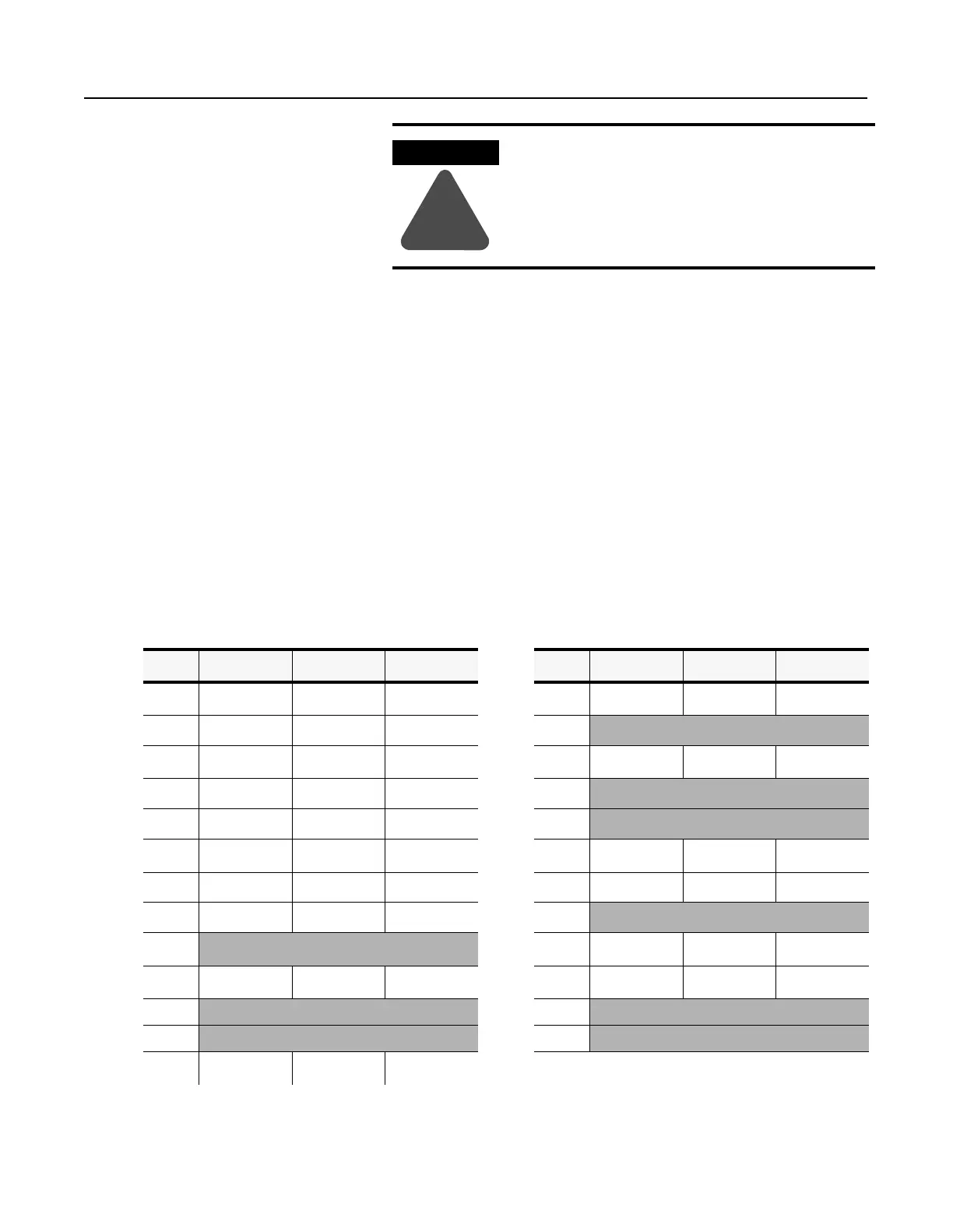
The side label of the processor shows the following table, which
lists Channel 0 (serial port) pin assignments.
When used in a Class I, Division 2, hazardous
location, this equipment must be mounted in a
suitable enclosure with proper wiring method that
complies with the governing electrical codes.
WARNING
!
Pin RS-232C RS-422A RS-423 Pin RS-232C RS-422A RS-423
1 C.GND C.GND C.GND 14 NOT USED
TXD.OUT
-
SEND COM
2 TXD.OUT
TXD.OUT
+
TXD.OUT 15
3 RXD.IN
RXD.IN
+
RXD.IN 16 NOT USED
RXD.IN
-
REC COM
4 RTS.OUT
RTS.OUT
+
RTS.OUT 17
5 CTS.IN
CTS.IN
+
CTS.IN 18
6 DSR.IN
DSR.IN
+
DSR.IN 19 NOT USED
RTS.OUT
-
NOT USED
7 SIG.GND SIG.GND SIG.GND 20 DTR.OUT
DTR.OUT
+
DTR.OUT
8 DCD.IN
DCD.IN
+
DCD.IN 21
9 22 NOT USED
DSR.IN
-
NOT USED
10 NOT USED
DCD.IN
-
NOT USED 23 NOT USED
DTR.OUT
-
NOT USED
11 24
12 25
13 NOT USED
CTS.IN
-
NOT USED
The shading indicates that the pin is reserved.

 Loading...


