1785-UM022B-EN-P - February 2002
2-22 Planning to Use Your ControlNet PLC-5 Processor
Understanding Discrete Mapping
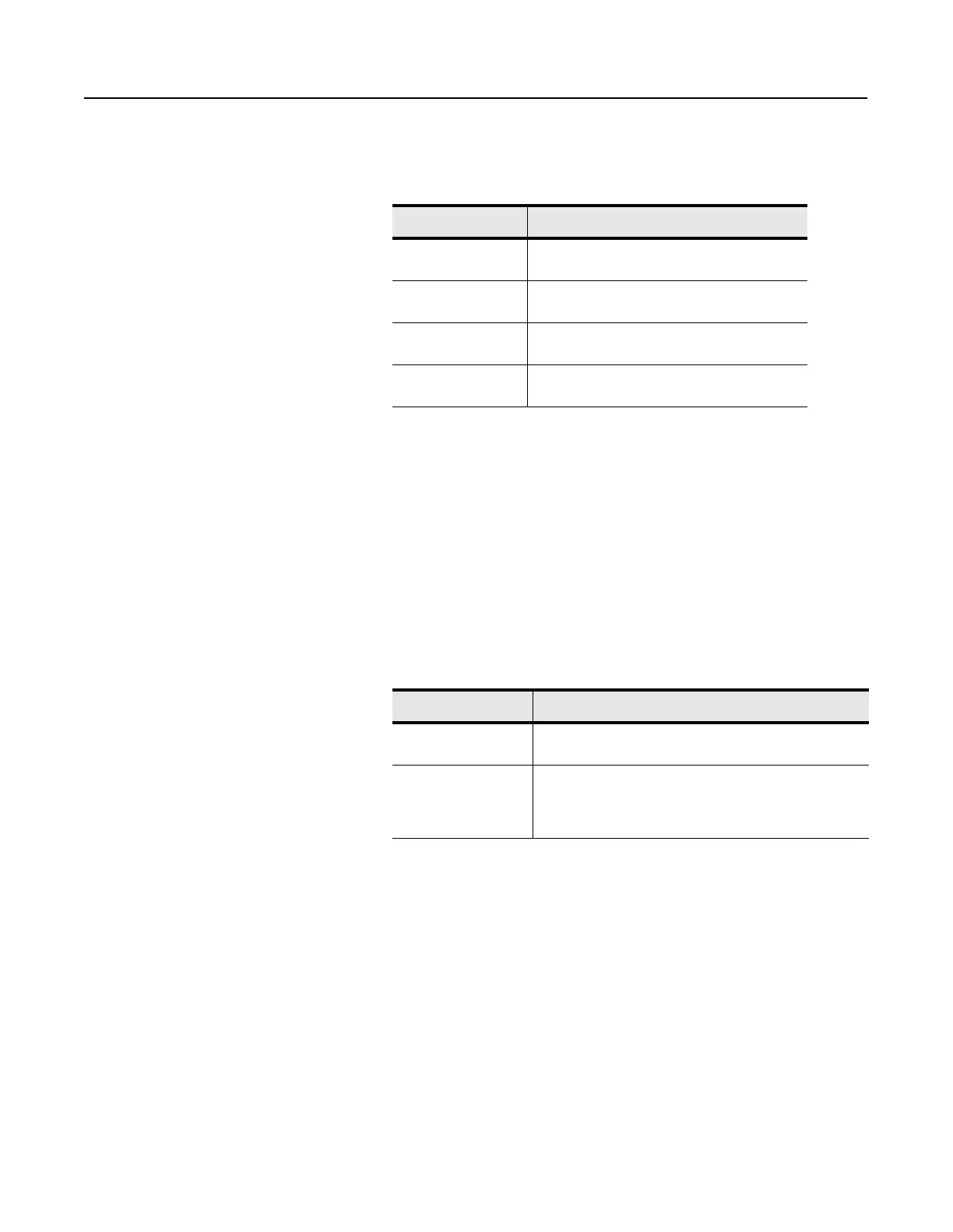
Each version of a PLC-5 processor has a fixed amount of I/O image
space. For example:
The I/O image table is used for all discrete I/O connected to the
PLC-5 processor, regardless of where it is located (local I/O, Remote
I/O, ControlNet network). Since the local chassis reserves a minimum
of eight words of input and output, a PLC-5/20C processor has a
maximum of 24 words of inputs and 24 words of outputs available for
the ControlNet network. Some applications may find that the use of
I/O image space needs to be optimized to insure that the I/O
requirements can be met.
A node address on a ControlNet network does not directly map to a
location in the I/O image table like it does on a Remote I/O network.
For example, If you have an 8-slot chassis in 1-slot addressing and set
the node address to two, and:
For example, you can specify I:024 as the input location and O:032 as
the output location. The only restriction is that you must map the
input and output words contiguously. If you mapped eight words of
inputs you must map it to a location with eight words available. In
this example, words I:024-I:033 must be available.
The ControlNet network also allows the size of the chassis to be set
based on what is needed. Using the previous example, the chassis on
the Remote I/O network uses eight words of inputs and eight words of
outputs, regardless of what modules are actually in the chassis. On the
ControlNet network, you can set the sizes to what is actually needed.
For example, you can set the input size to six and the output size to
three. If no outputs are in the chassis you can set the output size to
zero.
This processor: Has:
PLC-5/20C 32 words of input image table and 32 words of
output image table
PLC-5/40C 128 words of input image table and 128 words of
output image table
PLC-5/46C 128 words of input image table and 128 words of
output image table
PLC-5/80C 192 words of input image table and 192 words of
output image table
If the node is on a: Then:
Remote I/O network the inputs in that chassis automatically map to I:020-I:027 if the
node is on a remote I/O network
ControlNet network you can map the inputs to any location available in the input
image table, and the outputs to any location available in the
output image table. The input and output locations can be in
two totally different rack numbers.

 Loading...


