Installing Your Module
Chapter 2
2-10
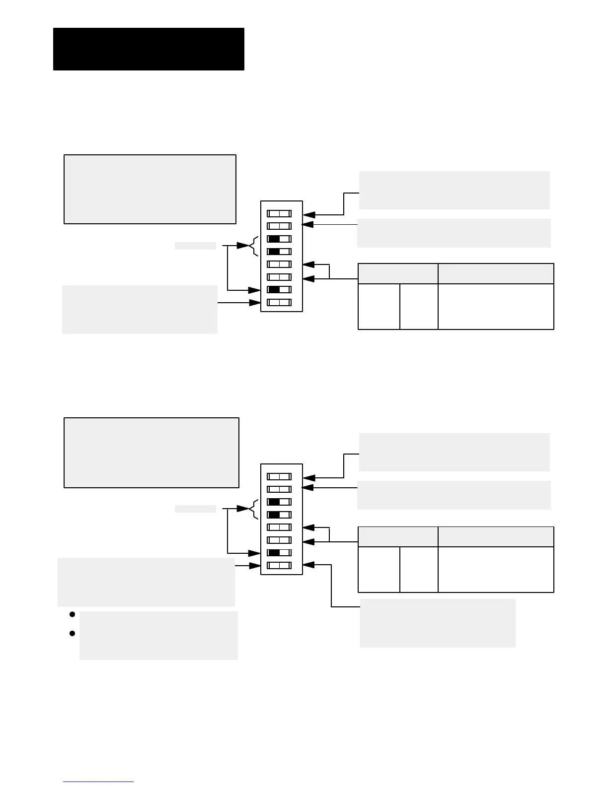
Figure 2.9
I/O
Chassis Backplane Switch Assembly Settings for Remote Adapter
Module in PLC3 Family Processor System
Processor Restart Lockout
When ON, processor can restart I/O chassis
When OFF, I/O chassis must be restarted at the chassis.
Last State Switch
When ON, outputs of this chassis remain in last state.
When OFF, outputs of this I/O chassis are deenergized
when a fault is detected.
Always OFF
10802I
ATTENTION: Set switch 1 to the OFF position
to deenergize outputs wired to this chassis when
a fault is detected. If switch 1 is set to the ON
position, outputs connected to this chassis remain
in their last state when a fault occurs and machine
motion may continue after fault detection.
O
O
12 3456 78
N
F
F
OFF ON You select 1/2slot addressing
ON OFF You select 1slot addressing
OFF OFF You select 2slot addressing
ON ON Not allowed
Addressing Switches
56
1771A1/A1B chassis in PLC3 Backup
ON If any 1771A1/A1B chassis contains
starting I/O group 0 with 2slot addressing
and the PLC3 is configured in backup mode.
OFF All other times.
Figure 2.10
I/O
Chassis Backplane Switch Assembly Settings for Remote Adapter
Module in PLC5 Family Processor System
Processor Restart Lockout
When ON, processor can restart I/O chassis
When OFF, I/O chassis must be restarted at the chassis.
Last State Switch
When ON, outputs of this chassis remain in last state.
When OFF, outputs of this I/O chassis are deenergized
when a fault is detected.
Always OFF
10802I
ATTENTION: Set switch 1 to the OFF position
to deenergize outputs wired to this chassis when a
fault is detected. If switch 1 is set to the ON
position, outputs connected to this chassis remain
in their last state when a fault occurs and machine
motion may continue after fault detection.
O
O
12 3456 78
N
F
F
OFF ON You select 1/2slot addressing
ON OFF You select 1slot addressing
OFF OFF You select 2slot addressing
ON ON Not allowed
Addressing Switches
56
1771A1/A1B chassis in PLC3 Backup
ON If any 1771A1/A1B chassis contains
starting I/O group 0 with 2slot addressing
and the PLC3 is configured in backup mode.
OFF All other times.
Last Chassis Switch
ON Chassis does not contain the highest
numbered I/O group for the associated rack number
OFF Chassis does contain the highest numbered
I/O group for the associated rack number
If you have only a primary chassis, set this
switch to OFF.
If you have both primary and complementary
chassis, set the primary chassis to ON and the
complementary chassis to OFF.
 Loading...


