Installing Your Module
Chapter 2
2-11
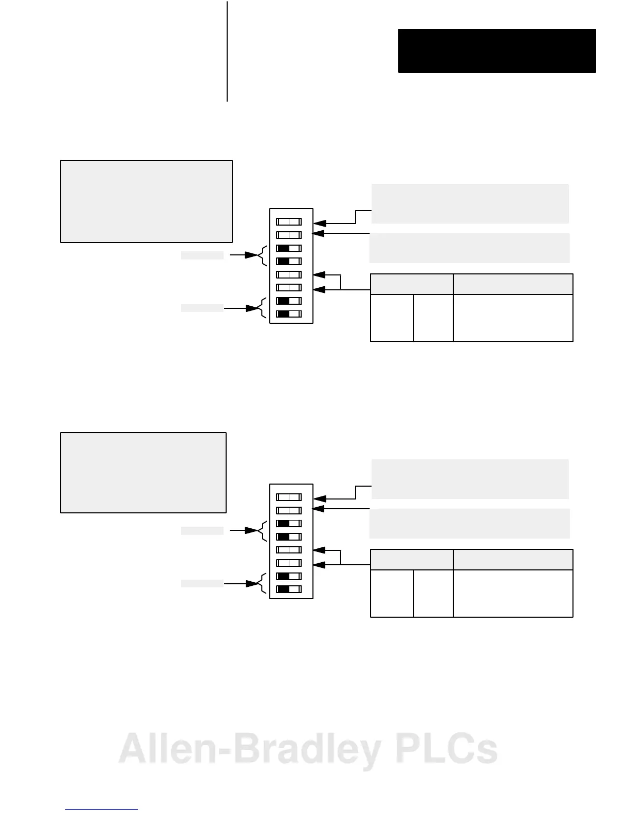
Figure 2.11
I/O
Chassis Backplane Switch Assembly Settings for Remote Adapter
Module in PLC5 Family Processor System in Remote Configuration
Processor Restart Lockout
When ON, processor can restart I/O chassis
When OFF, I/O chassis must be restarted at the chassis.
Last State Switch
When ON, outputs of this chassis remain in last state.
When OFF, outputs of this I/O chassis are deenergized
when a fault is detected.
Always OFF
10802I
O
O
12 3456 78
N
F
F
OFF ON You select 1/2slot addressing
ON OFF You select 1slot addressing
OFF OFF You select 2slot addressing
ON ON Not allowed
Addressing Switches
56
Always OFF
ATTENTION: If switch 1 is set to the ON
position, outputs connected to this chassis
remain in their last state when a fault occurs
and machine motion may continue after fault
detection. We recommend that you set switch 1
to the OFF position to deenergize outputs wired
to this chassis when a fault is detected.
Figure 2.12
I/O
Chassis Backplane Switch Assembly Settings for Remote Adapter
Module in PLC5/250 Processor System
Processor Restart Lockout
When ON, processor can restart I/O chassis
When OFF, I/O chassis must be restarted at the chassis.
Last State Switch
When ON, outputs of this chassis remain in last state.
When OFF, outputs of this I/O chassis are deenergized
when a fault is detected.
Always OFF
10802I
O
O
12 3456 78
N
F
F
OFF ON You select 1/2slot addressing
ON OFF You select 1slot addressing
OFF OFF You select 2slot addressing
ON ON Not allowed
Addressing Switches
56
Always OFF
ATTENTION: Set switch 1 to the OFF position
to deenergize outputs wired to this chassis
when a fault is detected. If switch 1 is set to the
ON position, outputs connected to this chassis
remain in their last state when a fault occurs
and machine motion may continue after fault
detection.
Allen-Bradley PLCs
 Loading...


