Chapter 3
Addressing Modes for Your Remote I/O
3-7
Identifying I/O Groups
You identify your I/O groups in one of three ways, depending on the
addressing method and I/O chassis you use. Refer to:
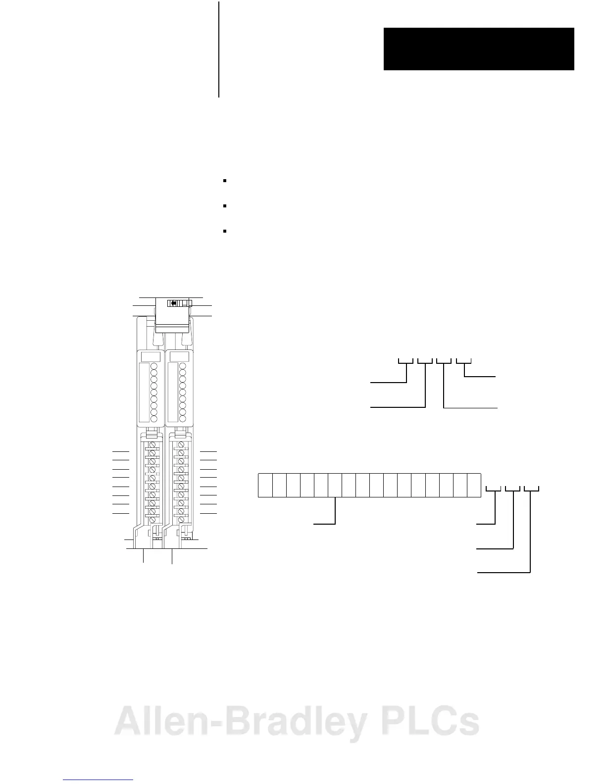
Figure 3.6 for 2-slot addressing when using series A I/O chassis.
Figure 3.7 for 2-slot addressing when using series B I/O chassis.
Figure 3.13 for 1-slot addressing when using series B I/O chassis.
Figure 3.6
Identifying
2slot I/O Groups with Series A I/O Chassis
Input
Terminals
00
01
02
03
04
05
06
07
Output
Terminals
10
11
12
13
14
15
16
17
2-slot
I/OGroup
Type of I/O module
1 = Input
0 = Output
I/O Rack Number
Physical Address
Module
Terminal
Number
I/O Group
Number
17 161514 12
10
07
06
05 03
020100
04
11
13
Inputimagetablewordcorresponding
totheI/Ogroup.
Left
Slot
Right
Slot
0
00071017
11012
Module
Terminal
Number
Type of I/O module
1 = Input
0 = Output
I/O Rack Number
110
I/O Group
Number
Example: Using I/O Group 0, a sample physical address
(with its corresponding data table address) is:
10808I
Allen-Bradley PLCs
 Loading...


