Addressing Modes for Your Remote I/O
Chapter 3
3-8
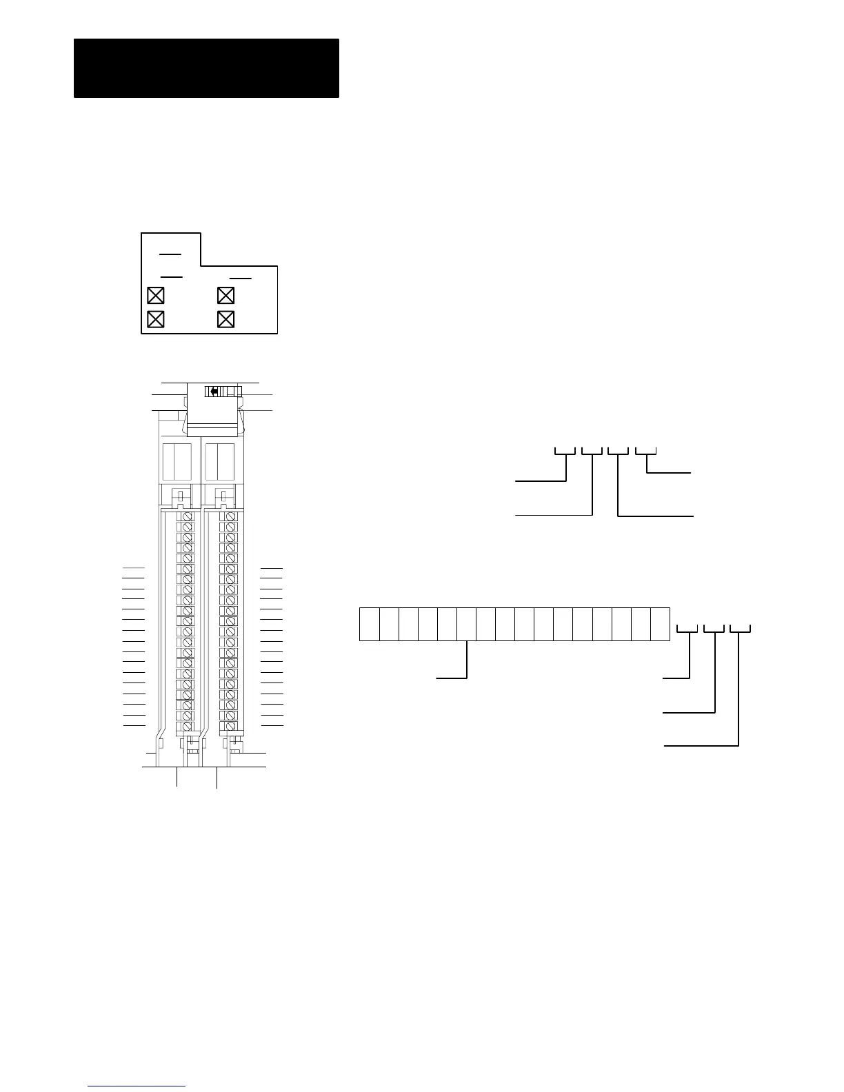
Figure 3.7
Identifying
2slot I/O Groups with Series B I/O Chassis
Type of I/O module
1 = Input
0 = Output
I/O Rack Number
Physical Address
Module
Terminal
Number
I/O Group
Number
17 16 15 14 12
10
07
06
05 03
02 01 00
04
11
13
Input image table word corresponding
to the I/O group.
Left
Slot
Right
Slot
11 012
Module
Terminal
Number
Type of I/O module
1 = Input
0 = Output
I/O Rack Number
11 0
I/O Group
Number
Example: Using I/O Group 0 and 16point modules, a sample
physical address (with its corresponding data table address) is:
00
01
02
03
04
05
06
07
10
11
12
13
14
15
16
17
00
01
02
03
04
05
06
07
10
11
12
13
14
15
16
17
Input
Terminals
Output
Terminals
2-slot I/O Group
R
G
G
0007
1017
0007
1017
1
0
0
Rules for module terminal point assignments are:
Standard density discrete I/O module in the left slot
has terminals numbered 0007. (Mark top only.)
Standard density discrete I/O module in the right slot
has terminals numbered 1017. (Mark bottom only.)
High density (16point) discrete I/O module in either slot
has terminals numbered 0007 and 1017.
10809I
 Loading...


