Settings for 1771-AS and 1771-ASB
Series A, B and C Remote I/O Adapters
Appendix B
B-2
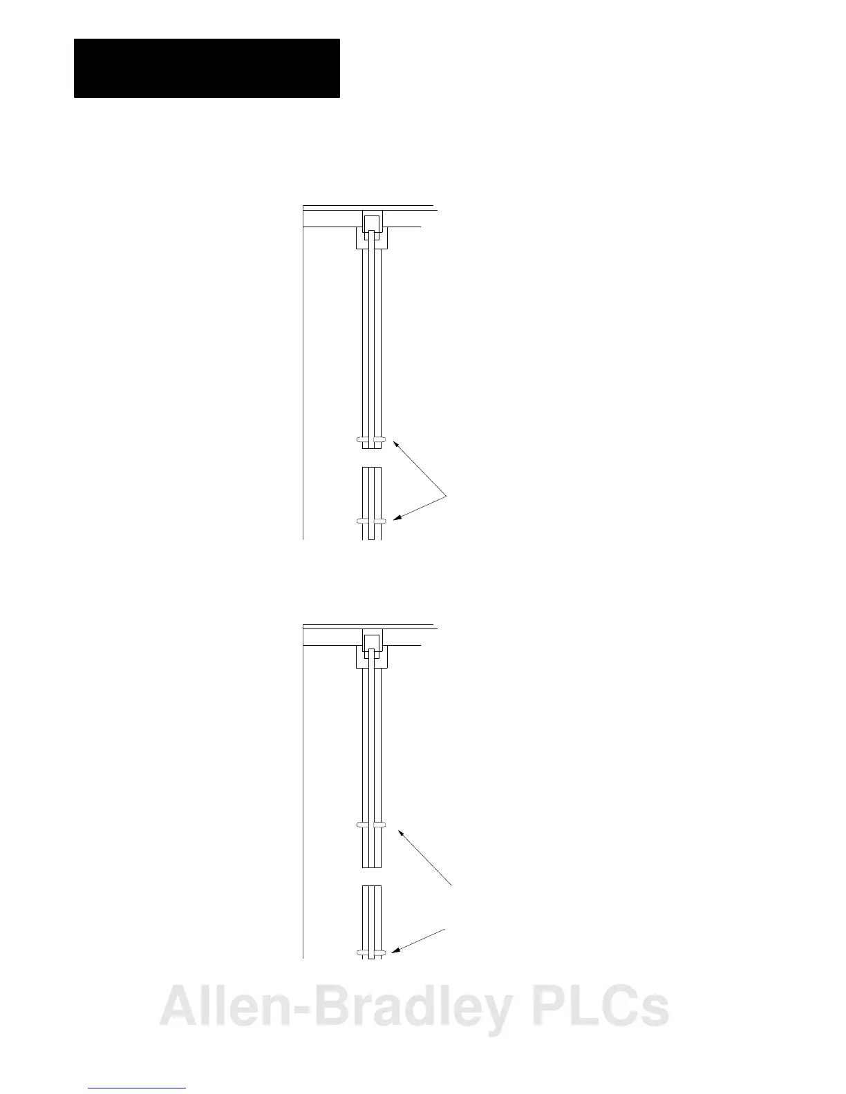
Figure B.1
Keying
Diagram for 1771-ASB series A, B and C
2
4
6
8
10
12
14
16
18
20
22
24
26
28
30
32
34
36
38
40
42
44
46
48
50
52
54
56
2
4
6
8
10
12
14
16
8
0
22
Insert keying bands between:
upper connector - 54 and 56
lower connector - 16 and 18
2
1
12252
Figure B.2
Keying
Diagram for 1771-AS Remote I/O Adapter
2
4
6
8
10
12
14
16
18
20
22
24
26
28
30
32
34
36
38
40
42
44
46
48
50
52
54
56
2
4
6
8
10
12
14
16
8
0
22
Insert keying bands between:
upper connector - 44 and 46
lower connector - 20 and 22
2
1
12252
Allen-Bradley PLCs
 Loading...


