Settings for 1771-AS and 1771-ASB
Series A, B and C Remote I/O Adapters
Appendix B
B-3
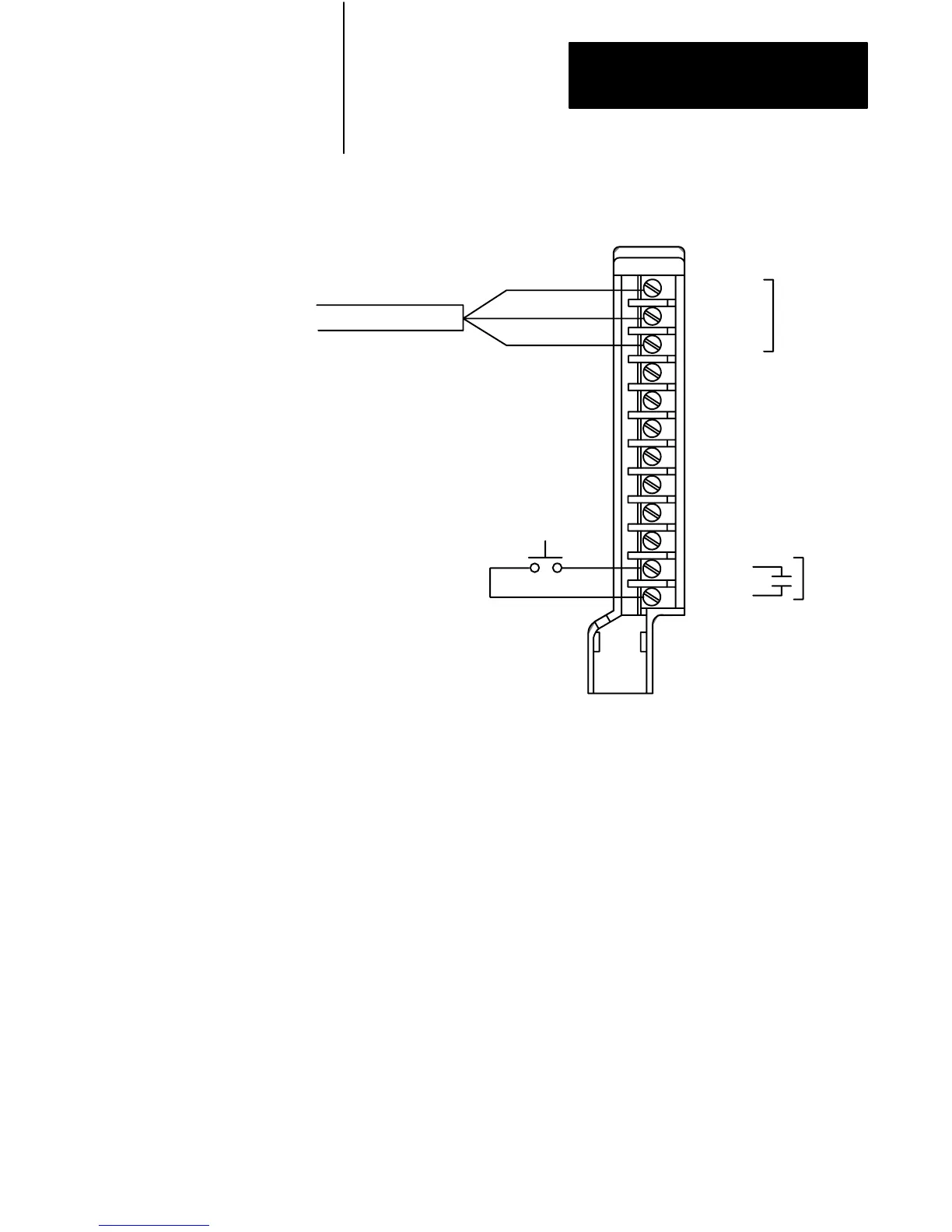
Figure B.3
Field
W
iring Arm Connection Diagram for 1771-AS, -ASB series A, B
and C
1 Line 1
2 Shield
3 Line 2
4 No connection
5 No connection
6 No connection
7 No connection
8 No connection
9 No connection
10 No connection
11 In
12 Ret
Reset
User supplied
I/O rack restart
pushbutton
Allen-Bradley Cable (cat. no. 1770-CD)
Blue
Shield
Clear
1
2
3
4
5
6
7
8
9
10
11
12
Cable
17343
WARNING: Do not make connections to terminals
4
through
10. These terminals are connected internally (1 to 4,
2 to 5 and 3 to 6) and cannot be used for any other purpose.
 Loading...


