Installing the 1203-GK5 Module or 1336-GM5 Board 3-5
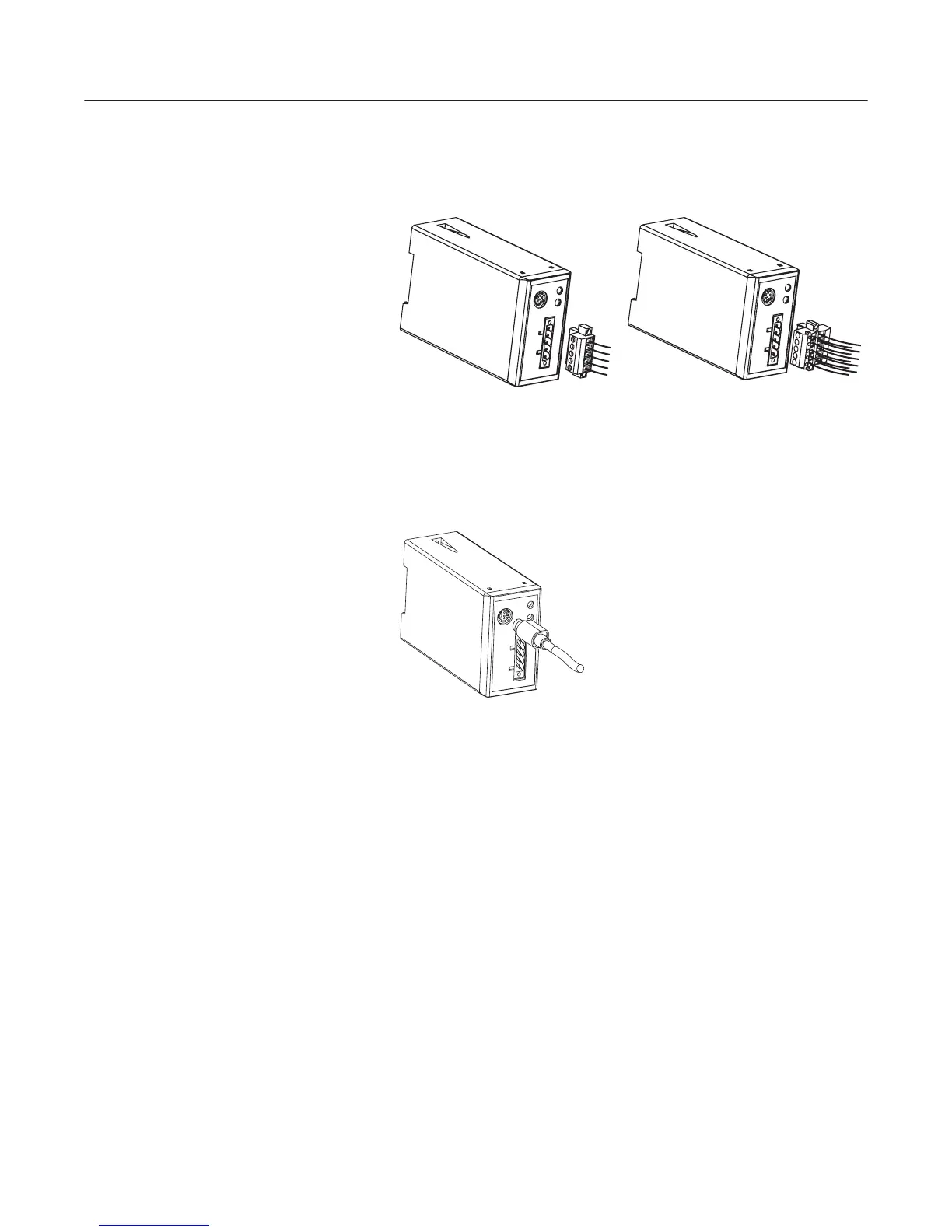
4. Plug the DeviceNet cable into the module. Make sure that you
use the color key next to the connector receptacle on the module.
Figure 3.4
Inserting a 5-pin or 10-pin Phoenix Connector
5. Screw the two screws into place using a 1/8" flathead screwdriver.
6. Connect the SCANport cable to the communications adapter and
then to the SCANport product.
Figure 3.5
Inserting the SCANport Cable
7. Reapply power to the network.
8. If necessary, apply power to the connected SCANport product.
Your 1203-GK5 module is now installed. The SCANport LED is
solid green. The network LED is blinking green. You are now ready
to configure the scanner to communicate with the module. Refer to
Chapter 4, Configuring a Scanner to Communicate with the 1203-
GK5 Module or 1336-GM5 Board.
Important: If your LEDs are different, refer to Chapter 7,
Troubleshooting, for more information.
AB0942
AB0943
efesotomasyon.com - Allen Bradley,Rockwell,plc,servo,drive
 Loading...


