3-8 Installing the 1203-GK5 Module or 1336-GM5 Board
Installing the 1336-GM5 Communications Board
The following instructions explain how to physically install a
DeviceNet 1336-GM5 communications board.
Important: If you are attaching the communications board to a 1336
PLUS II, refer to the one-page insert included with the kit for
mounting instructions.
Important: To prevent damage to the board, you must wear a
grounding wrist strap when handling the 1336-GM5 communications
board.
1. Remove power from the product, and verify that the drive is not
holding power.
2. Remove power from the DeviceNet network.
3. Screw the four stand-off nylon headers into the appropriate
spaces on the drive main control board.
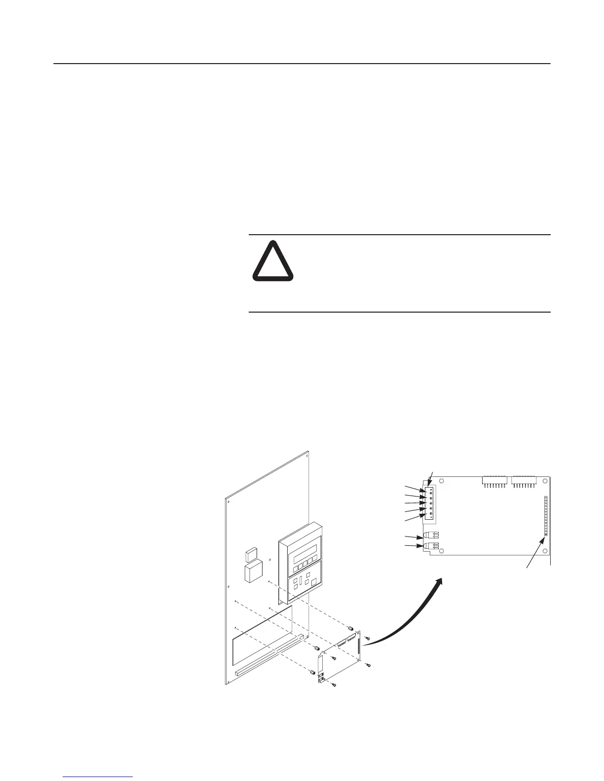
Figure 3.7
Mounting the Open Style Communications Board
!
ATTENTION: Remove all power from the SCANport
product before installing the 1336-GM5 board. Failure
to disconnect power may result in death or serious injury.
Verify all power is removed before installing the
1336-GM5 board.
DeviceNet
Connector
Internal SCANport
Connector
Black - V -
Blue - CAN_L
Bare - Shield
White - CAN_H
Red - V+
DeviceNet Status
SCANport Status
AB0945
efesotomasyon.com - Allen Bradley,Rockwell,plc,servo,drive
 Loading...


