Publication 1762-RM001C-EN-P
Using High-Speed Outputs 6-13
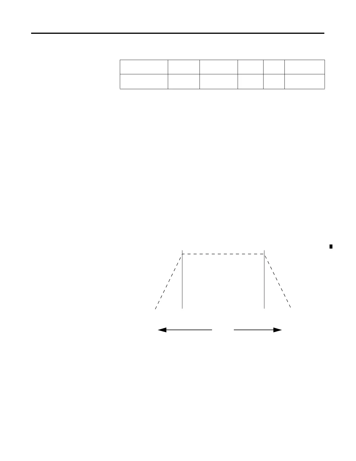
PTO Accel / Decel Pulses (ADP)
The PTO ADP (Accel/Decel Pulses) defines how many of the total pulses
(TOP variable) will be applied to each of the ACCEL and DECEL
components.
The illustration below shows the relationship, where:
•
TOP (total output pulses) = 12,000
•
ADP (accelerate/decelerate pulses)= 3,000
If you need to determine the ramp period (accelerate/decelerate ramp
duration):
•
2 x ADP/OF = duration in seconds (OF = output frequency)
The following formulas can be used to calculate the maximum frequency
limit for both profiles. The maximum frequency = the integer
≤
the result
found below (OF = output frequency):
•
For Trapezoid Profiles: OF x OF/4 + 0.5
•
For S-Curve Profiles: 0.999 x OF x SQRT(OF/6)
The ADP range is from 0 to the calculated value. The value in the ADP
variable must be less than one-half the value in the TOP variable, or an
error is generated. In this example, the maximum value that could be
used for accelerate/decelerate is 6000, because if both accelerate and
decelerate are 6000, the total number of pulses = 12,000. The run
component would be zero. This profile would consist of an acceleration
phase from 0 to 6000. At 6000, the output frequency (OF variable) is
generated and immediately enters the deceleration phase, 6000 to 12,000.
At 12,000, the PTO operation would stop (output frequency = 0).
Sub-Element
Description
Address Data Format Range Type User Program
Access
ADP - Accel/Decel
Pulses
PTO:0.ADP long word (32-bit
INT)
see below control read/write
Accel Run Decel
3,000 6,000 3,000
Accel Run Decel
12,000

 Loading...


