Publication 1762-RM001C-EN-P
Using High-Speed Outputs 6-15
PTO Jog Frequency (JF)
The PTO JF (Jog Frequency) variable defines the frequency of the PTO
output during all Jog phases. This value is typically determined by the
type of device that is being driven, the mechanics of the application, or
the device/components being moved). Data less than zero and greater
than 20,000 generates a PTO error.
PTO Jog Pulse (JP)
The PTO JP (Jog Pulse) bit is used to instruct the PTO sub-system to
generate a single pulse. The width is defined by the Jog Frequency
parameter in the PTO function file. Jog Pulse operation is only possible
under the following conditions:
•
PTO sub-system in idle
•
Jog continuous not active
•
Enable not active
The JP bit operates as follows:
•
Set (1) - Instructs the PTO sub-system to generate a single Jog Pulse
•
Cleared (0) - Arms the PTO Jog Pulse sub-system
PTO Jog Pulse Status (JPS)
The PTO JPS (Jog Pulse Status) bit is controlled by the PTO sub-system. It
can be used by an input instruction on any rung within the control
program to detect when the PTO has generated a Jog Pulse.
The JPS bit operates as follows:
•
Set (1) - Whenever a PTO instruction outputs a Jog Pulse
•
Cleared (0) - Whenever a PTO instruction exits the Jog Pulse state
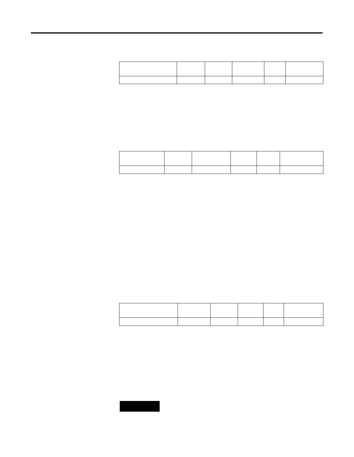
Sub-Element
Description
Address Data
Format
Range Type User Program
Access
JF - Jog Frequency (Hz) PTO:0.JF word (INT) 0 to 20,000 control read/write
Sub-Element
Description
Address Data Format Range Type User Program
Access
JP - Jog Pulse PTO:0/JP bit 0 or 1 control read/write
Sub-Element
Description
Address Data
Format
Range Type User Program
Access
JPS - Jog Pulse Status PTO:0/JPS bit 0 or 1 status read only
NOTE
The output (jog) pulse is normally complete with the JP
bit set. The JPS bit remains set until the JP bit is cleared (0
= off).

 Loading...


