Publication 1762-RM001C-EN-P
21-20 Communications Instructions
Remote Bridge Address
This variable defines the remote node address of the bridge device. In this
example, the remote bridge address is set to zero, because the target
device, SLC 5/04 at node 63 (octal) is a remote-capable device. If the
target device is remote-capable, the remote bridge address is not required.
If the target device is not remote-capable (SLC 500, SLC 5/01, SLC 5/02,
and MicroLogix 1000 Series A, B and C), the remote bridge address is
required.
Remote Station Address
This variable is the final destination address of the message instruction. In
this example, integer file 50 elements 0 to 4 of the SLC 5/04 on Link ID
100 at node 63 (octal) receives data from the MicroLogix 1500 controller at
node 12 on Link ID 1.
Remote Bridge Link ID
This variable is a user-assigned value that defines the remote network as a
number. This number must be used by any device initiating remote
messaging to that network. In the example, any controller on Link ID 1
sending data to a device on Link ID 100 must use the remote bridge link
ID of the passthru device. In this example, the SLC 5/04 on Link ID1,
node 17 is the passthru device.
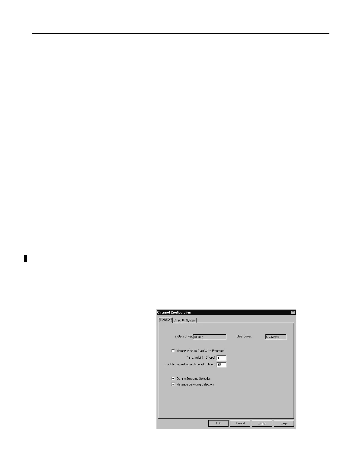
Passthru Link ID
Set the Passthru Link ID in the General tab on the Channel Configuration
screen. The Link ID value is a user-defined number between 1 and
65,535. All devices that can initiate remote messages and are connected to
the local network must have the same number for this variable.

 Loading...


