Publication 1762-RM001C-EN-P
5-10 Using the High-Speed Counter
Low Preset Interrupt (LPI)
The LPI (Low Preset Interrupt) status bit is set (1) when the HSC
accumulator reaches the low preset value and the HSC interrupt has been
triggered. This bit can be used in the control program to identify that the
low preset condition caused the HSC interrupt. If the control program
needs to perform any specific control action based on the low preset, this
bit would be used as conditional logic.
This bit can be cleared (0) by the control program and is also be cleared
by the HSC sub-system whenever these conditions are detected:
•
High Preset Interrupt executes
•
Underflow Interrupt executes
•
Overflow Interrupt executes
•
Controller enters an executing mode
Low Preset Reached (LPR)
The LPR (Low Preset Reached) status flag is set (1) by the HSC sub-system
whenever the accumulated value (HSC:0.ACC) is less than or equal to the
low preset variable (HSC:0.LOP).
This bit is updated continuously by the HSC sub-system whenever the
controller is in an executing mode.
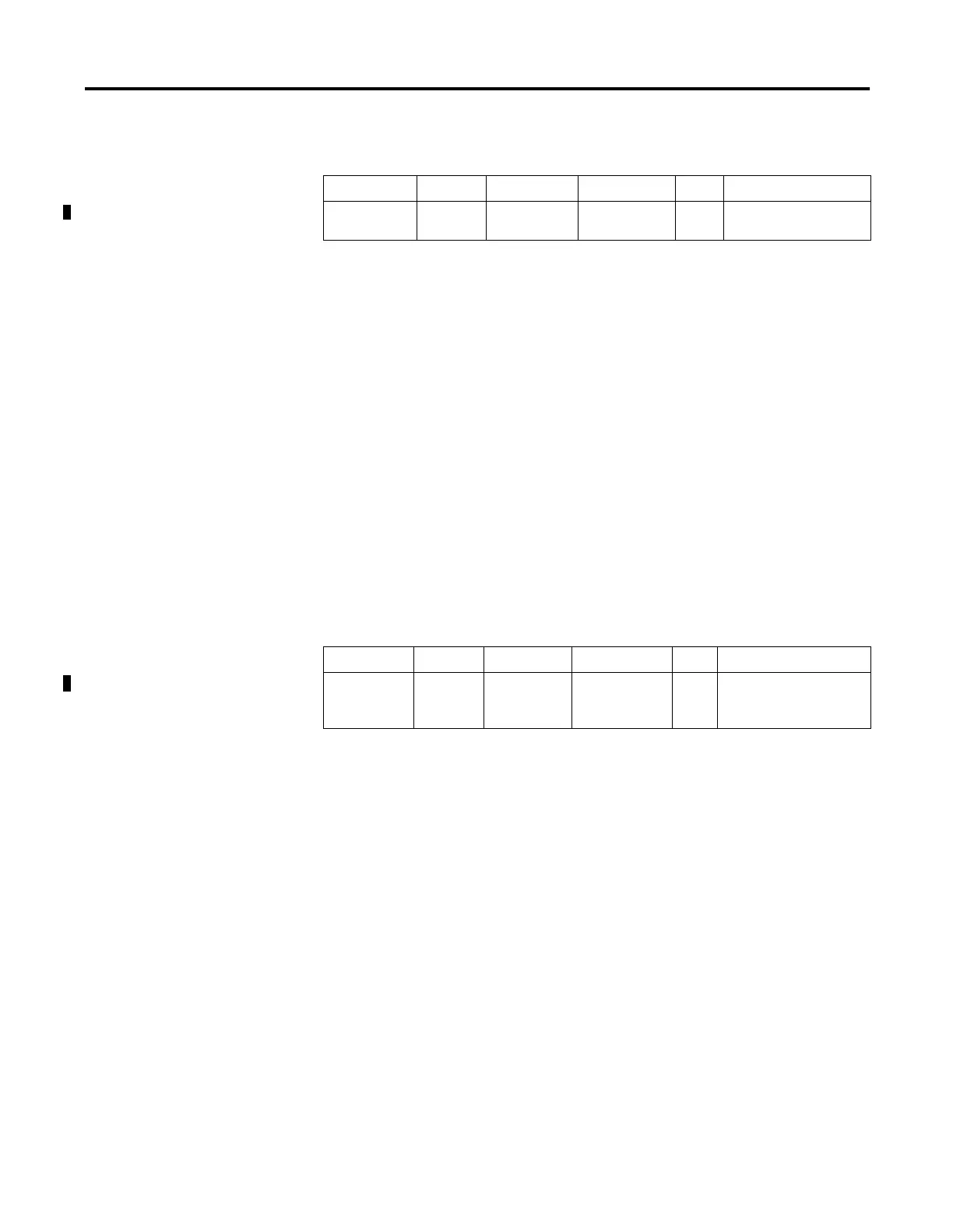
Description Address Data Format
HSC Modes
(1)
(1) For Mode descriptions, see HSC Mode (MOD) on page 5-16.
Type User Program Access
LPI - Low
Preset Interrupt
HSC:0/LPI bit 2 to 7 status read/write
Description Address Data Format
HSC Modes
(1)
(1) For Mode descriptions, see HSC Mode (MOD) on page 5-16.
Type User Program Access
LPR - Low
Preset
Reached
HSC:0/LPR bit 2 to 7 status read only

 Loading...


