Publication 1762-RM001C-EN-P
5-12 Using the High-Speed Counter
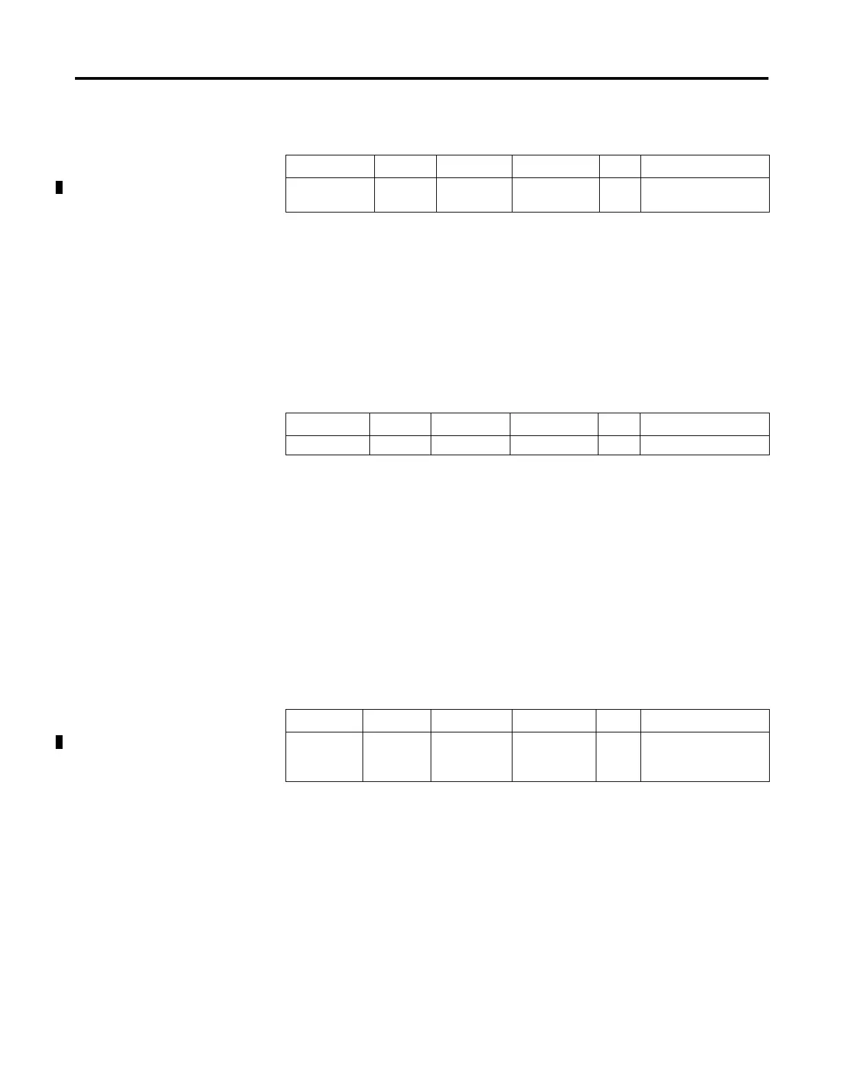
High Preset Reached (HPR)
The HPR (High Preset Reached) status flag is set (1) by the HSC
sub-system whenever the accumulated value (HSC:0.ACC) is greater than
or equal to the high preset variable (HSC:0.HIP).
This bit is updated continuously by the HSC sub-system whenever the
controller is in an executing mode.
Underflow (UF)
The UF (Underflow) status flag is set (1) by the HSC sub-system whenever
the accumulated value (HSC:0.ACC) has counted through the underflow
variable (HSC:0.UNF).
This bit is transitional and is set by the HSC sub-system. It is up to the
control program to utilize, track if necessary, and clear (0) the underflow
condition.
Underflow conditions do not generate a controller fault.
Underflow Mask (UFM)
The UFM (Underflow Mask) control bit is used to enable (allow) or
disable (not allow) a underflow interrupt from occurring. If this bit is clear
(0), and a Underflow Reached condition is detected by the HSC, the HSC
user interrupt is not executed.
This bit is controlled by the user program and retains its value through a
power cycle. It is up to the user program to set and clear this bit.
Description Address Data Format
HSC Modes
(1)
(1) For Mode descriptions, see HSC Mode (MOD) on page 5-16.
Type User Program Access
HPR - High
Preset Reached
HSC:0/HPR bit 2 to 7 status read only
Description Address Data Format
HSC Modes
(1)
(1) For Mode descriptions, see HSC Mode (MOD) on page 5-16.
Type User Program Access
UF - Underflow HSC:0/UF bit 0 to 7 status read/write
Description Address Data Format
HSC Modes
(1)
(1) For Mode descriptions, see HSC Mode (MOD) on page 5-16.
Type User Program Access
UFM -
Underflow
Mask
HSC:0/UFM bit 2 to 7 control read/write

 Loading...


