16 MicroLogix 1762-IF4 Analog Input Module
Publication 1762-IN012C-EN-P - June 2013
Labeling the Terminals
A write-on label is provided with the module. Mark the identification of each terminal with
permanent ink, and slide the label back into the door.
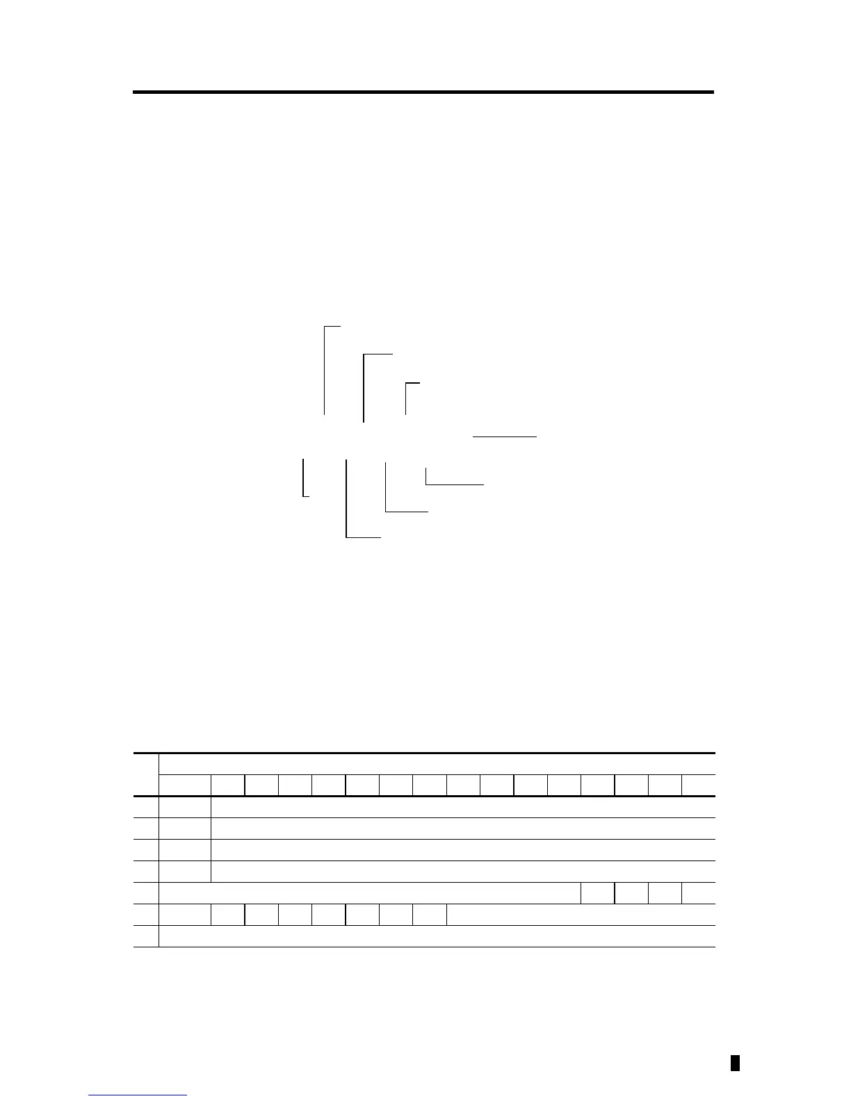
1762 Expansion I/O Addressing
The addressing scheme for 1762 Expansion I/O is represented in the following figure.
Input Data File
For each module, slot x, words 0…3 contain the analog values of the inputs. The module can be
configured to use either raw/proportional data or scaled-for-PID data. The input data file for
either configuration is shown below.
Word
Bit Position
15 14 13 12 11 10 9 8 7 6 5 4 3 2 1 0
0 SGN0 Channel 0 Data
1 SGN1 Channel 1 Data
2 SGN2 Channel 2 Data
3 SGN3 Channel 3 Data
4 reserved S3 S2 S1 S0
5U0 O0U1O1U2O2U3O3reserved
6 reserved
I1:x.0/0
Slot number
(1)
Data file
Input
Slot delimiter
Word delimiter
Bit delimiter
Bit (0...15)
Word
(1)
I/O located on the controller (embedded I/O) is slot 0. I/O added to the controller (expansion I/O) begins with slot 1.

 Loading...


