70 Rockwell Automation Publication 2711R-UM001E-EN-E - January 2017
Chapter 4 Cable Connections and Communication
Connecting Devices
Use these cables for connecting devices to PanelView 800 terminals.
MicroLogix Controller
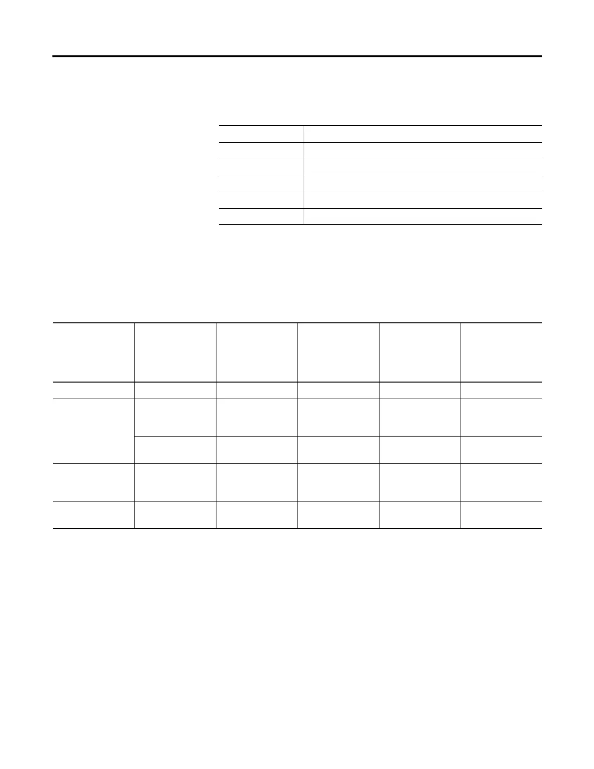
Cable Charts
The chart provides a summary of terminal connections to controllers and
network interface modules.
Cables for PanelView 800 Terminals
Cat. No. Description
2711P-CBL-EX04 Ethernet crossover CAT5 cable 4.3 m (14 ft)
1747-CP3 Serial 9-pin D-shell to 9-pin D-shell null modem cable
1761-CBL-PM02 Serial 9-pin D-shell to 8-pin mini DIN cable, 2 m (6.56 ft)
2711C-CBL-AB03 RS-485 5-pin to RJ45 cable
1763-NC01 Series A 8-pin Mini DIN to 6-pin RS-485 terminal block
PanelView 800 Terminal Connections to MicroLogix Controllers
Protocol PanelView 800
Port
MicroLogix
(8-pin Mini DIN)
1000, 1100, 1400,
1200LSP, 1500LSP
(Ch 0)
MicroLogix
(9-pin D-shell)
1500LRP (Ch 1)
MicroLogix
1100/1400 RS485
(1763-NC01)
MicroLogix
1100/1400 Ethernet
DF1 RS-232 1761-CBL-PM02 1747-CP3 N/A N/A
DH-485 RS-232 1761-CBL-PM02 1747-CP3 Use AIC+ module
(1761-NET-AIC)
connect to port 3
N/A
RS-485
(1)
N/A N/A Belden 3106A or
#9842 or equivalent
N/A
Modbus RS-232 1761-CBL-PM02 1747-CP3 Use AIC+ module
(1761-NET-AIC)
connect to port 3
N/A
Ethernet
(MicroLogix/ENI)
Ethernet N/A N/A N/A CAT 5 Ethernet
(1)
RS485 is isolated. It is recommended to only connect one device. Multi-node communication is supported when appropriate hardware, such as 1747-AIC or AIC+ is added
to the wiring.

 Loading...