Analog Inputs 7
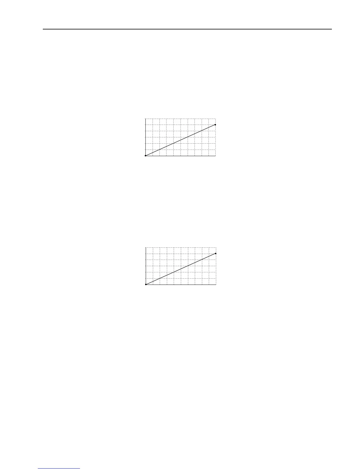
Example 6
− [Anlg In Config], bit 0 = “0” (Voltage)
− [Speed Ref A Sel] = “Analog In 1”
− [Speed Ref A Hi] = 60 Hz
− [Speed Ref A Lo] = 0 Hz
− [Analog In 1 Hi] = 5V
− [Analog In 1 Lo] = 0V
This configuration is used when the input signal is 0-5 volts. Here, minimum input (0 Volts) represents 0
Hz and maximum input (5 Volts) represents 60 Hz. This allows full scale operation from a 0-5 volt
source.
Example 7
− [Anlg In Config], bit 0 = “0” (Voltage)
− [Torque Ref A Sel] = “Analog In 1”
− [Torque Ref A Hi] = 200%
− [Torque Ref A Lo] = 0%
− [Torque Ref A Div] = 1 (PowerFlex 700VC Only)
This configuration is used when the input signal is 0-10 volts. The minimum input of 0 volts represents
a torque reference of 0% and maximum input of 10 volts represents a torque reference of 200%.
1
2
3
4
5
6
601218
Output Hertz
Input Volts
24 30 36 42 48 54 60
2
4
6
8
10
12
2004060
Torque Ref %
Input Volts
80 100 120 140 160 180 200

 Loading...


