78 Process PID Loop
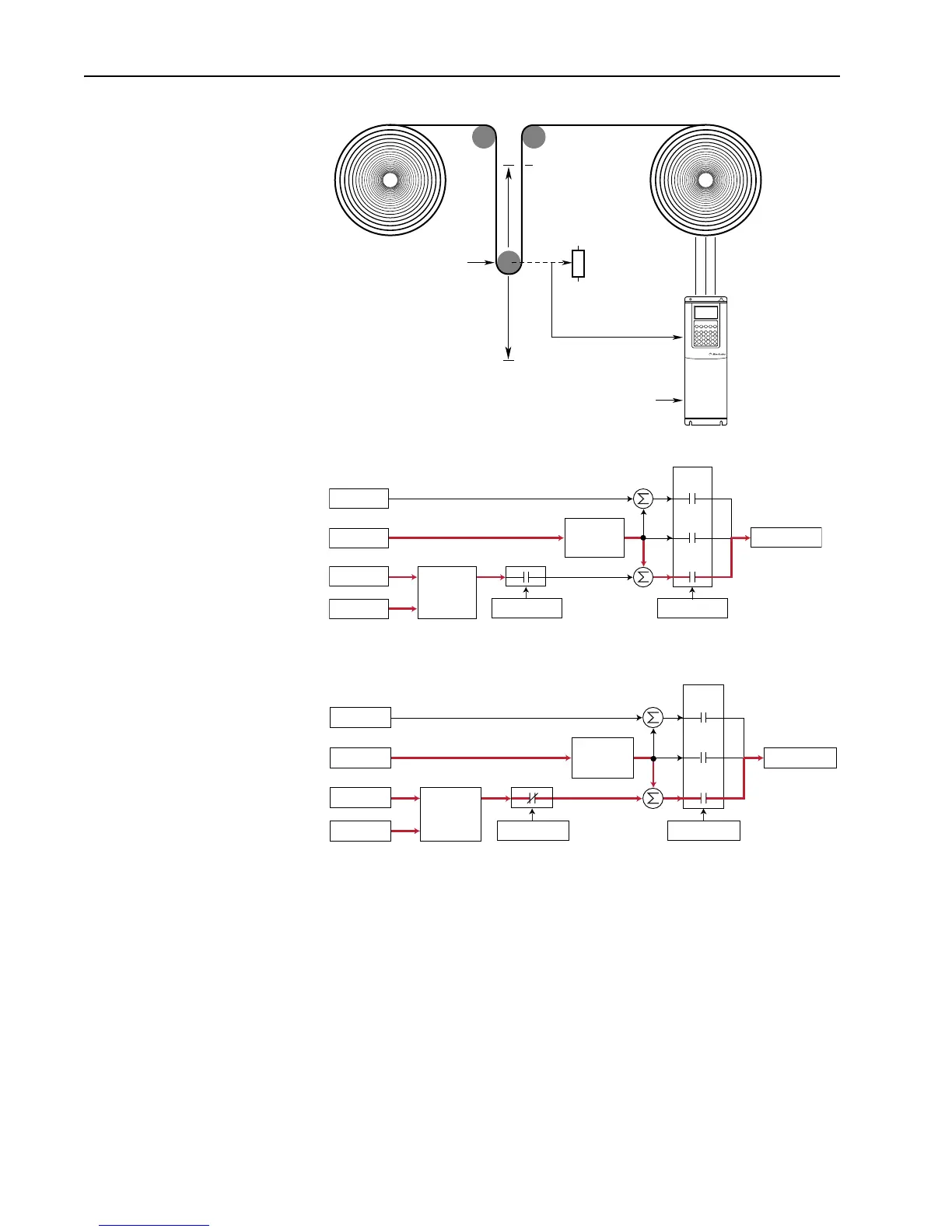
When the PID is disabled the commanded speed is the ramped speed reference.
When the PID is enabled, the output of the PID Controller is added to the ramped
speed reference.
Exclusive Mode
In this mode, the output of PID regulator is the speed reference, and does not “trim”
a master speed reference. This mode is appropriate when speed is unimportant and
the only thing that matters is satisfying the control loop. In the pumping application
example below, the reference or setpoint is the required pressure in the system. The
input from the transducer is the PID feedback and changes as the pressure changes.
The drive output frequency is then increased or decreased as needed to maintain
system pressure regardless of flow changes. With the drive turning the pump at the
required speed, the pressure is maintained in the system.
Master Speed Reference
10 Volts
0 Volts
Dancer Pot
[PI Feedback Sel]
Equilibrium Point
[PI Reference Sel]
+
Spd Cmd
Process PI
Controller
Linear Ramp
& S-Curve
+
+
+
PI Disabled
Speed Control
Spd Ref
PI Ref
PI Fbk
Slip Adder
Open
Loop
Slip
Comp
Process
PI
+
Spd Cmd
Process PI
Controller
Linear Ramp
& S-Curve
+
+
+
PI Enabled
Speed Control
Spd Ref
PI Ref
PI Fbk
Slip Adder
Open
Loop
Slip
Comp
Process
PI

 Loading...


