EasyManua.ls Logo

Allen-Bradley PowerFlex 70 Enhanced Control User Manual

Allen-Bradley PowerFlex 70 Enhanced Control
170 pages
To Next Page IconTo Next Page
To Previous Page IconTo Previous Page
Page #9 background imageLoading...
Page #9 background image
Analog Inputs 5
Example 1
[Anlg In Config], bit 0 = “0” (Voltage)
[Speed Ref A Sel] = “Analog In 1”
[Speed Ref A Hi] = 60 Hz
[Speed Ref A Lo] = 0 Hz
[Analog In 1 Hi] = 10V
[Analog In 1 Lo] = 0V
This is the default setting, where 0 volts represents 0 Hz and 10 volts represents 60 Hz providing 1024
steps (10 bit analog input resolution) between 0 and 60 Hz.
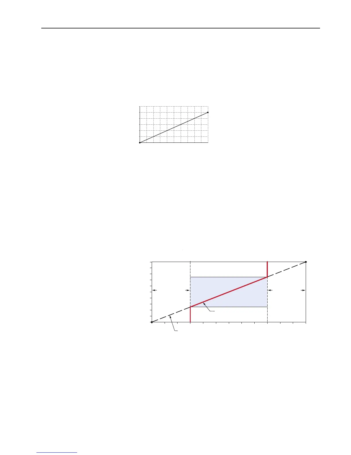
Example 2
Consider the following setup:
[Anlg In Config], bit 0 = “0” (voltage)
[Speed Ref A Sel] = “Analog In 1”
[Analog In1 Hi] = 10V
[Analog In1 Lo] = 0V
[Speed Ref A Hi] = 60 Hz
[Speed Ref A Lo] = 0 Hz
[Maximum Speed] = 45 Hz
[Minimum Speed] = 15 Hz
This configuration is used when non-default settings are desired for minimum and maximum speeds,
but full range (0-10V) scaling from 0-60 Hz is still desired.
In this example, a deadband from 0-2.5 volts and from 7.5-10 volts is created. Alternatively, the analog
input deadband could be eliminated while maintaining the 15 and 45 Hz limits with the following
changes:
[Speed Ref A Lo] = 15 Hz
[Speed Ref A Hi] = 45 kHz
2
4
6
8
10
12
601218
Output Hertz
Input Volts
24 30 36 42 48 54 60
Motor Operating Range
Command Frequency
15 Hz 45 Hz 60 Hz0 Hz
Frequency Deadband
Slope defined by (Analog Volts)/(Command Frequency)
Frequency Deadband
7.5-10 Volts0-2.5 Volts
[Speed Ref A Lo] [Speed Ref A Hi]
10V
0V
[Analog In1 Hi]
[Analog In1 Lo]
[Maximum Speed][Minimum Speed]
Question and Answer IconNeed help?

Do you have a question about the Allen-Bradley PowerFlex 70 Enhanced Control and is the answer not in the manual?

Allen-Bradley PowerFlex 70 Enhanced Control Specifications

General IconGeneral
BrandAllen-Bradley
ModelPowerFlex 70 Enhanced Control
CategoryDC Drives
LanguageEnglish

Summary

Important User Information

Preface

Overview

Provides general information about the manual's scope and conventions.

Reference Information

General Precautions

Highlights essential precautions for safe installation, operation, and maintenance.

Detailed Drive Operation

Explains drive functions, organized alphabetically by topic.

Analog Inputs

Details possible uses and scaling configurations for analog inputs.

Manual Conventions

Explains symbols and text conventions used throughout the manual.

Accel/Decel Time

Sets the rate at which the drive ramps output frequency after start/stop.

Analog Outputs

Describes analog output configurations, scaling, and examples.

Auto/Manual

Explains the function for temporary override of speed and start/stop control.

Auto Restart

Describes the drive's ability to automatically reset faults and restart.

Autotune

Details parameters determined by autotune tests for motor identification.

Bus Regulation

Explains how the drive regulates excess voltage on the DC bus.

Current Limit

Describes methods the drive uses to protect against overcurrent situations.

Digital Inputs

Details the configuration and function of digital inputs.

Digital Outputs

Describes programming digital outputs based on various drive conditions.

Direction Control

Explains how drive direction is controlled via various inputs and methods.

Drive Overload

Details the drive's overload function with inverse time and thermal manager.

Faults

Details conditions causing faults, fault queue, and clearing procedures.

Flying Start

Details the feature for starting into a rotating motor, resuming normal operation.

Motor Control Modes

Selects drive output mode: V/Hz, Sensorless Vector, Flux Vector, etc.

Motor Overload

Details the drive's overload function with inverse time and thermal manager.

Notch Filter

Reduces mechanical resonance in the torque reference loop.

Position Indexer/Speed Profiler

Configures the drive as a velocity or position regulator with programmable steps.

Speed Reference

Selects the speed reference source from digital inputs or network commands.

Speed Regulation

Adjusts output frequency to compensate for load changes and maintain speed.

Stop Modes

Describes various methods for braking or stopping a load with the drive.

User Display

Allows programming the display to show pertinent information when keys are inactive.

Voltage Class

Identifies the general input voltage range to the drive.

Voltage Tolerance

Defines the acceptable input voltage ranges for drive operation.

Appendix

Supplemental Information

Provides additional technical details and parameter explanations.

Engineering Parameters

Lists and describes parameters related to motor control and utility functions.

Related product manuals