EasyManuals Logo

Allen-Bradley PowerFlex 70 Reference Manual

Allen-Bradley PowerFlex 70
300 pages
To Next Page IconTo Next Page
To Previous Page IconTo Previous Page
Page #167 background imageLoading...
Page #167 background image
Process PI Loop 2-139
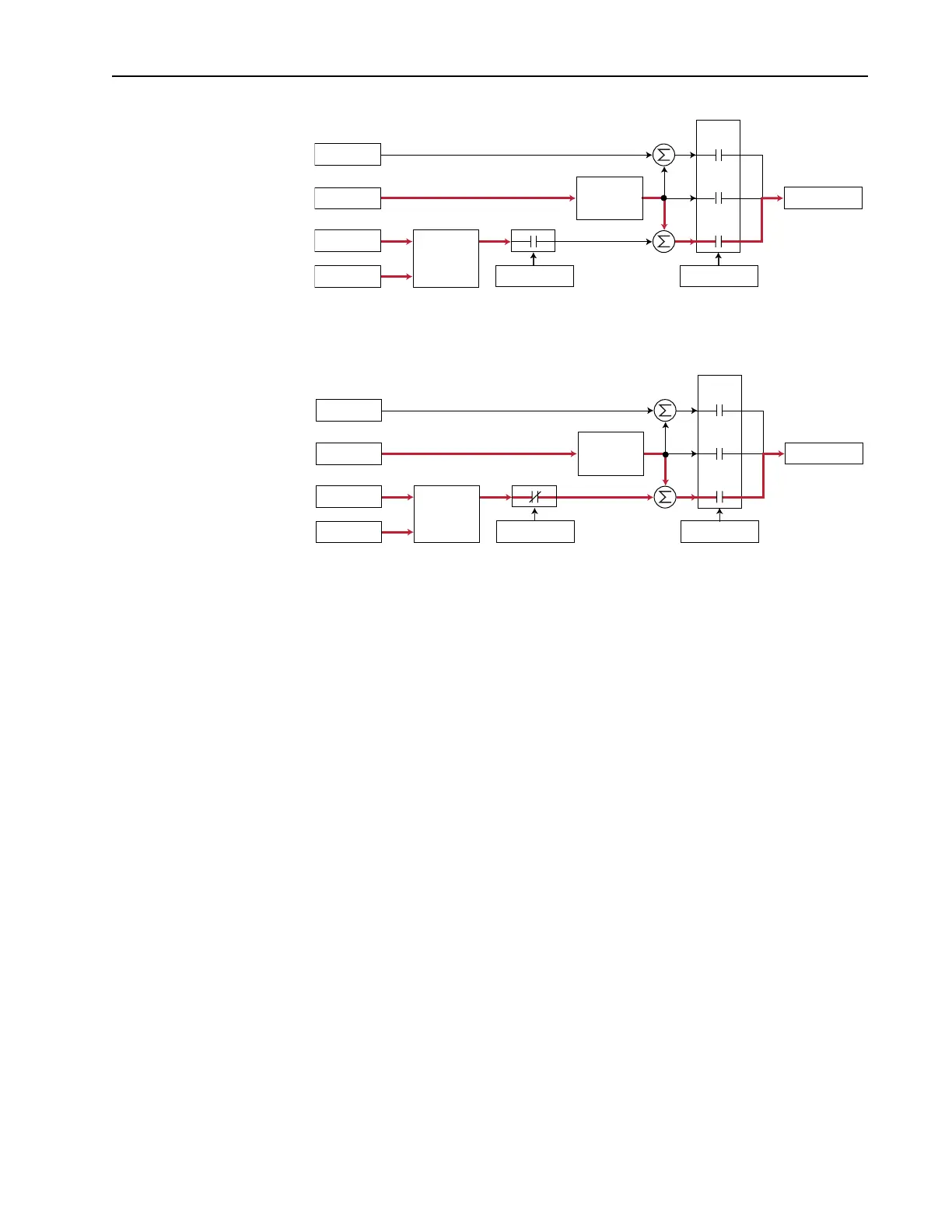
When the PI is enabled, the output of the PI Controller is added to the
ramped speed reference.
Exclusive Control
Process Control takes the output of PI regulator as the speed command. No
master speed reference exists and the PI Output directly controls the drive
output.
In the pumping application example below, the reference or setpoint is the
required pressure in the system. The input from the transducer is the PI
feedback and changes as the pressure changes. The drive output frequency
is then increased or decreased as needed to maintain system pressure
+
Spd Cmd
Process PI
Controller
Linear Ramp
& S-Curve
+
+
+
PI Disabled
Speed Control
Spd Ref
PI Ref
PI Fbk
Slip Adder
Open
Loop
Slip
Comp
Process
PI
+
Spd Cmd
Process PI
Controller
Linear Ramp
& S-Curve
+
+
+
PI Enabled
Speed Control
Spd Ref
PI Ref
PI Fbk
Slip Adder
Open
Loop
Slip
Comp
Process
PI

Table of Contents

Other manuals for Allen-Bradley PowerFlex 70

Questions and Answers:

Question and Answer IconNeed help?

Do you have a question about the Allen-Bradley PowerFlex 70 and is the answer not in the manual?

Allen-Bradley PowerFlex 70 Specifications

General IconGeneral
Input Voltage200-240V AC, 380-480V AC, 500-600V AC
Frequency Range0 - 400 Hz
Humidity5% to 95% non-condensing
Output Voltage0 to Input Voltage
Control MethodsSensorless Vector Control
CommunicationsEthernet/IP, DeviceNet, ControlNet
Protection FeaturesOvercurrent, Overvoltage, Undervoltage, Overtemperature, Ground Fault
Operating Temperature0°C to 50°C (32°F to 122°F)
Storage Temperature-40°C to 70°C (-40°F to 158°F)
Enclosure RatingIP20, NEMA Type 1

Related product manuals