EasyManuals Logo

Allen-Bradley PowerFlex 70 Reference Manual

Allen-Bradley PowerFlex 70
300 pages
To Next Page IconTo Next Page
To Previous Page IconTo Previous Page
Page #168 background imageLoading...
Page #168 background image
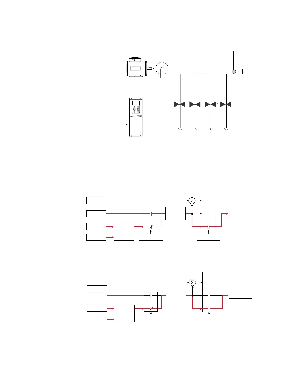
2-140 Process PI Loop
regardless of flow changes. With the drive turning the pump at the required
speed, the pressure is maintained in the system.
However, when additional valves in the system are opened and the pressure
in the system drops, the PI error will alter its output frequency to bring the
process back into control.
When the PI is disabled the commanded speed is the ramped speed
reference.
When the PI is enabled, the speed reference is disconnected and PI Output
has exclusive control of the commanded speed, passing through the linear
ramp and s-curve.
PI Feedback
Motor
Pump
Desired Pressure
[PI Reference Sel]
Pressure
Transducer
Spd Cmd
Process PI
Controller
Linear Ramp
& S-Curve
+
+
PI Disabled
Speed Control
Spd Ref
PI Ref
PI Fbk
Slip Adder
Open
Loop
Slip
Comp
Process
PI
Spd Cmd
Process PI
Controller
Linear Ramp
& S-Curve
+
+
PI Enabled
Speed Control
Spd Ref
PI Ref
PI Fbk
Slip Adder
Open
Loop
Slip
Comp
Process
PI

Table of Contents

Other manuals for Allen-Bradley PowerFlex 70

Questions and Answers:

Question and Answer IconNeed help?

Do you have a question about the Allen-Bradley PowerFlex 70 and is the answer not in the manual?

Allen-Bradley PowerFlex 70 Specifications

General IconGeneral
Input Voltage200-240V AC, 380-480V AC, 500-600V AC
Frequency Range0 - 400 Hz
Humidity5% to 95% non-condensing
Output Voltage0 to Input Voltage
Control MethodsSensorless Vector Control
CommunicationsEthernet/IP, DeviceNet, ControlNet
Protection FeaturesOvercurrent, Overvoltage, Undervoltage, Overtemperature, Ground Fault
Operating Temperature0°C to 50°C (32°F to 122°F)
Storage Temperature-40°C to 70°C (-40°F to 158°F)
Enclosure RatingIP20, NEMA Type 1

Related product manuals