Process PI Loop 2-145
may become enabled as soon as the drive goes into run. If analog
input signal loss is detected, the PI loop is disabled.
• PI Hold - The Process PI Controller has the option to hold the
integrator at the current value so if some part of the process is in limit
the integrator will maintain the present value to avoid windup in the
integrator.
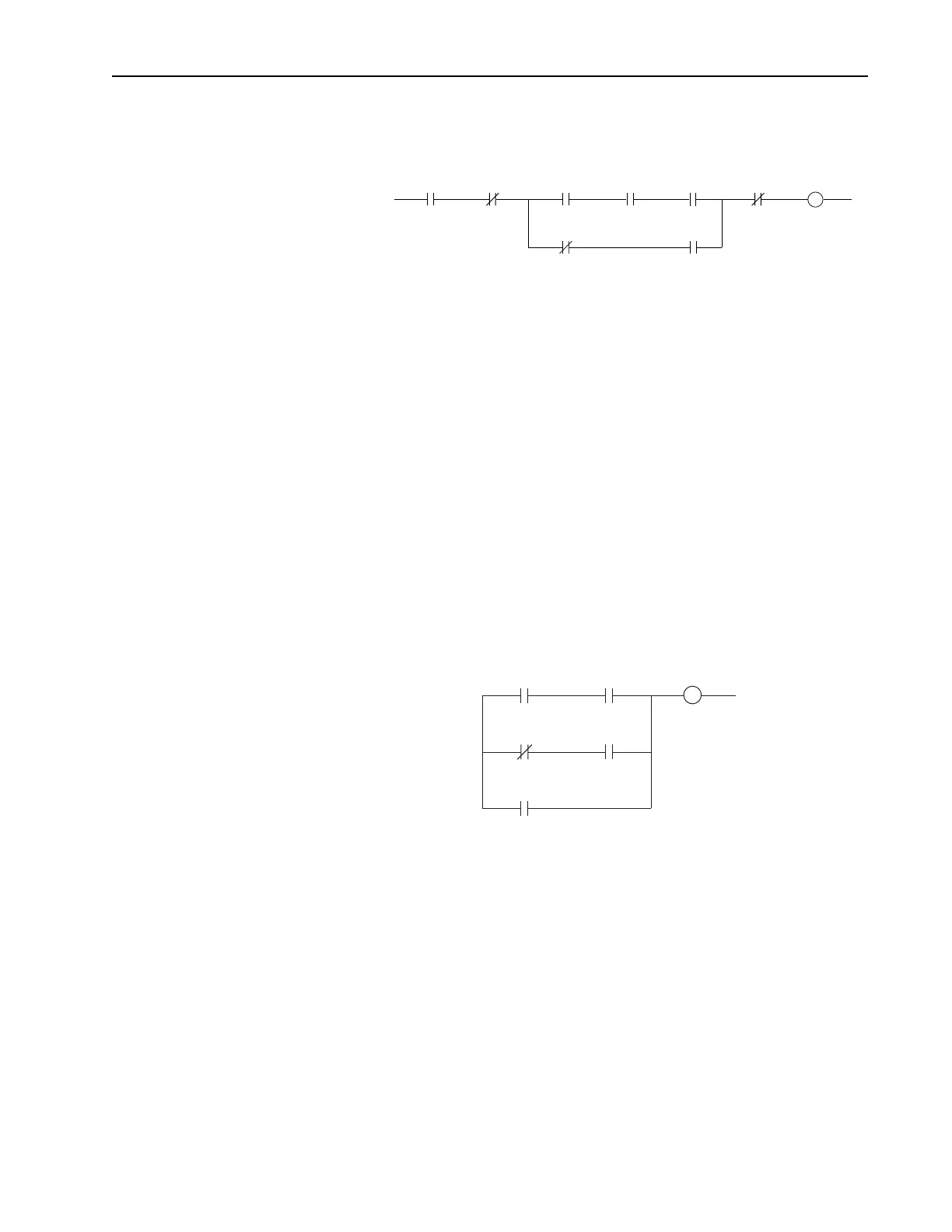
The logic to hold the integrator at the current value is shown in the
following ladder diagram. There are three conditions under which
hold will turn on.
– If a digital input is configured to provide PI Hold and that digital
input is turned on then the PI integrator will stop changing. Note that
when a digital input is configured to provide PI Hold that takes
precedence over the PI Control parameter.
– If a digital input is not configured to provide PI Hold and the PI Hold
bit in the PI Control parameter is turned on then the PI integrator will
stop changing.
– If the current limit or voltage limit is active then the PI is put into
hold.
• PI Reset – This feature holds the output of the integral function at
zero. The term “anti windup” is often applied to similar features. It
may be used for integrator preloading during transfer and can be used
to hold the integrator at zero during “manual mode”. Take the
example of a process whose feedback signal is below the reference
point, creating error. The drive will increase its output frequency in an
attempt to bring the process into control. If, however, the increase in
drive output does not zero the error, additional increases in output will
be commanded. When the drive reaches programmed Maximum
Frequency, it is possible that a significant amount of integral value
has been “built up” (windup). This may cause undesirable and sudden
operation if the system were switched to manual operation and back.
Resetting the integrator eliminates this windup.
Stopping
PI_Status
.Enabled
DigInCfg
.PI_Enable
DigInCfg
.PI_Enable
DigIn
.PI_Enable
PI_Control
.PI_Enable
PI_Control
.PI_Enable
Signal LossRunning
PI_Status
.Hold
DigInCfg
.PI_Hold
DigInCfg
.PI_Hold
DigIn
.PI_Hold
PI_Control
.PI_Hold
Current Lmt
or Volt Lmt
 Loading...


