2-202 Stop Modes
4. Ramp To Stop is selected by setting [Stop Mode x]. The drive will ramp
the frequency to zero based on the deceleration time programmed into
[Decel Time 1/2]. The “normal” mode of machine operation can utilize
[Decel Time 1]. If the “Machine Stop” mode requires a faster
deceleration than desired for normal mode, the “Machine Stop” can
activate [Decel Time 2] with a faster rate selected. When in Ramp to
Stop, the drive acknowledges the Stop command by decreasing or
“ramping” the output voltage and frequency to zero in a programmed
period (Decel Time), maintaining control of the motor until the drive
output reaches zero. The output transistors are then shut off.
The load/motor should follow the decel ramp. Other factors such as bus
regulation and current limit can alter the decel time and modify the ramp
function.
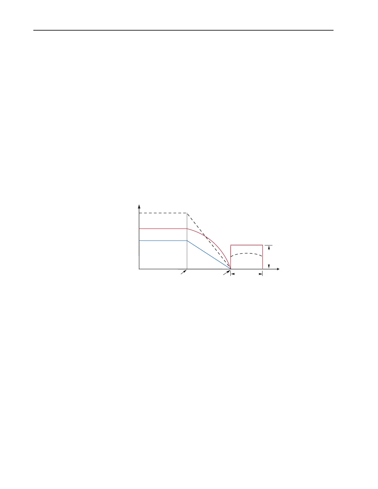
Ramp mode can also include a “timed” hold brake. Once the drive has
reached zero output hertz on a Ramp-to-Stop and both parameters [DC
Hold Time] and [DC Hold Level] are not zero, the drive applies DC to
the motor producing current at the DC Hold Level for the DC Hold
Time.
Motor speed during and after the application of DC depends upon the
combination of the these two parameter settings, and the mechanical
system. The drive output voltage will be zero when the hold time is
finished.
The level and uniformity of the DC braking offered at zero speed may
not be suitably smooth for many applications. If this is an application
requirement, a vector control drive, motion control drive or mechanical
brake should be used.
The drive output voltage will be zero when the hold time is finished
DC Hold Time
DC
Hold
Level
Stop
Command
Time
Output Voltage
Output Current
Motor Speed
Output Voltage
Output Current
Zero
Command
Speed

 Loading...


