Rockwell Automation Publication 20A-IN009E-EN-P - January 2015 21
PowerFlex 70 Adjustable Frequency AC Drive
Cable Entry Plate Removal
If more wiring access is needed, the cable entry plate on all drive frames can be
removed. Loosen the screws that secure the plate to the heat sink and slide out the
plate.
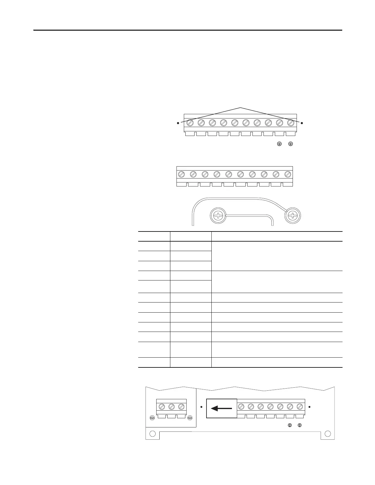
Figure 9 - Frame A, B, C, D Power Terminal Block and DC Bus Test Points
Figure 10 - Frame E Power Terminal Block
Figure 11 - Power Input Terminals on Frame B with Internal RFI Filter Option
Terminal Description Notes
R R (L1) Three-phase AC line input power.
For single-phase input, connect to any two terminals.
SS (L2)
TT (L3)
BR1 DC brake DB resistor connection - Important: Do not connect both an internal and
external DB resistor at the same time. This can violate the minimum
allowed DB resistance and cause damage to the drive.
BR2 DC brake
U U (T1) To the motor
V V (T2) To the motor
W W (T3) To the motor
PE PE ground –
PE PE ground –
-DC DC bus (–)
➊Test point on Frames A, B, C, and D are to the left or right of the power
terminal block. Frame E has a dedicated terminal.
+DC DC bus (+) –
L1
R
L2
S
L3
T
BR1
+DC
BR2
BRK
T1
U
T2
V
T3
W
PE PE
-DC
-DC
➊
L1
R
L2
S
L3
T
+DC –DC BR1 BR2 T1
U
T2
V
T3
W
PEPE
M6 M6
L1
R
L2
S
L3
T
BR1
+DC
BR2
BRK
T1
U
T2
V
T3
W
PE PE
-DC
-DC
L1
R
L2
S
L3
T

 Loading...


