Rockwell Automation Publication 20A-IN009E-EN-P - January 2015 35
PowerFlex 70 Adjustable Frequency AC Drive
Step 4: I/O Wiring
Important points to remember about I/O wiring:
• Use copper wire. Wire gauge requirements and recommendations are
based on 75 °C (167 °F). Do not reduce wire gauge when you are using
higher temperature wire.
• Wire with an insulation rating of 600V or greater.
• Control and signal wires must be separated from power wires by at least
0.3 m (1 ft).
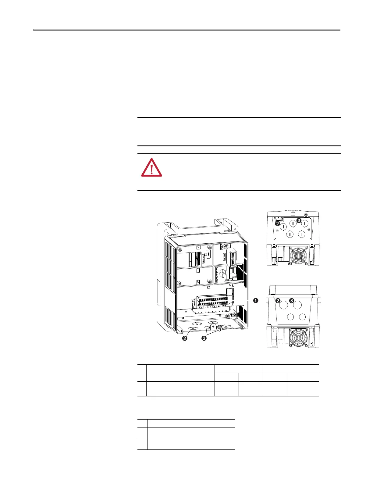
Figure 13 - Typical I/O Terminal Block Location (B Frame Shown)
Table 15 - I/O Terminal Block Specifications
Table 16 - Wire Routing Recommendations
I/O terminals that are labeled “(–)” Digital In Common or “Common” are not
connected to earth ground and are designed to greatly reduce common mode
interference. Grounding these terminals can cause signal noise.
ATTENTION: Hazard of personal injury or equipment damage exists when
using bipolar input sources. Noise and drift in sensitive input circuits can cause
unpredictable changes in motor speed and direction. Use speed command
parameters to help reduce input source sensitivity.
No. Name Description
Wire Size Range
(1)
(1) Maximum / minimum that the terminal block can accept - these are not recommendations.
Torque
Max Min Max Recommended
➊
I/O terminal
block
Signal and control
connections
1.5 mm
2
(16 AWG)
0.05 mm
2
(30 AWG)
0.55 N•m
(4.9 lb•in)
0.5 N•m
(4.4 lb•in)
No. Description
➋
Suggested entry for communication wiring.
➌
Suggested entry for I/O and control wiring.

 Loading...


