34 Rockwell Automation Publication 20A-IN009E-EN-P - January 2015
PowerFlex 70 Adjustable Frequency AC Drive
E B
D
E
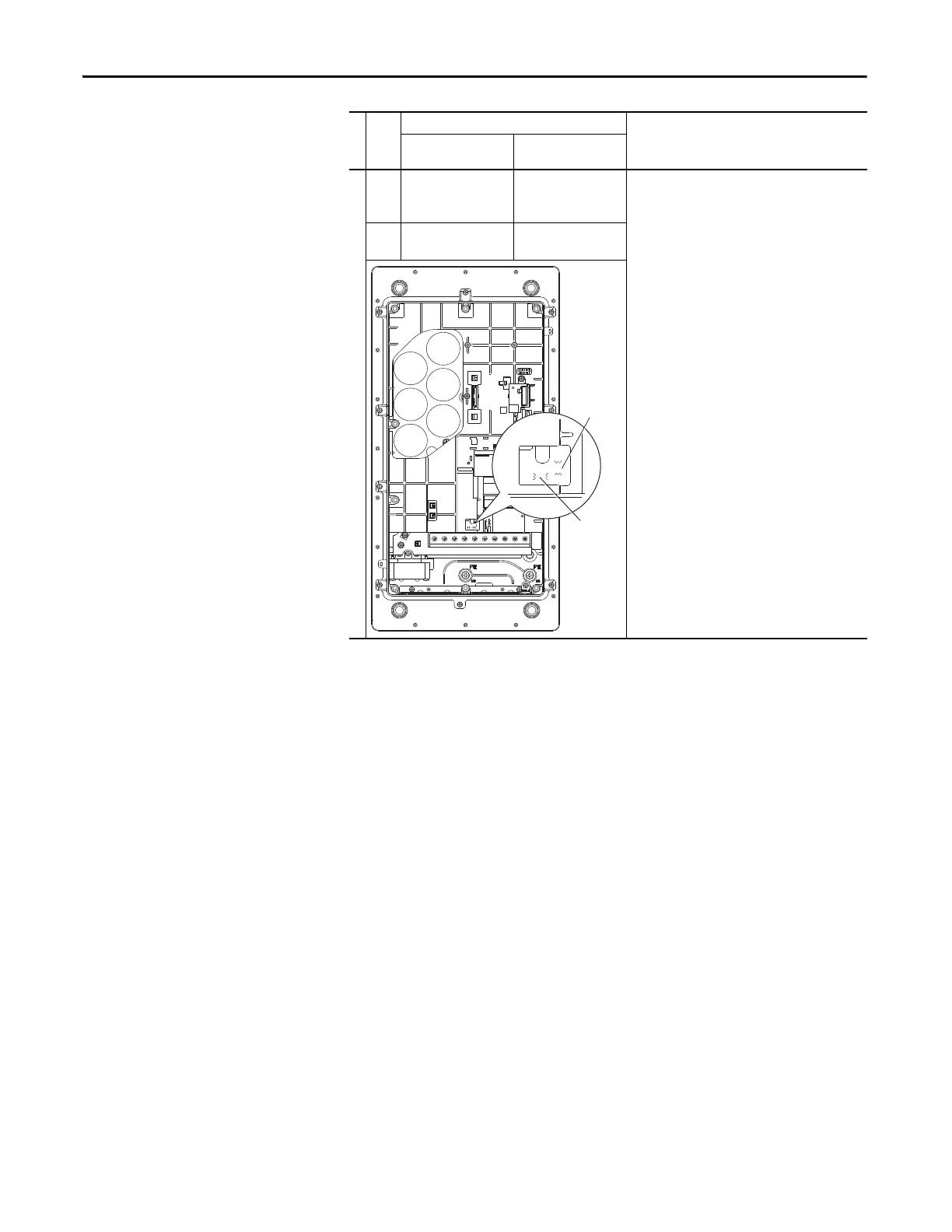
JP1/JP2
Installed
JP3/JP4
Installed
Solid ground
Verify that the jumpers at both locations (JP1/JP2 and
JP3/JP4) are installed.
Non-solid ground
Remove the jumpers at “JP1/JP2” and “JP3/JP4.”
C JP1/JP2
Installed
JP3/JP4
Installed
Frame
Voltage
Code
Factory Default Jumper Settings
Power Source TypeMOV/Input Filter Caps
DC Bus Common Mode
Caps
JP1 JP2
JP4
JP3
MOV /
Filter Cap
CM Cap

 Loading...


