Rockwell Automation Publication 20A-IN009E-EN-P - January 2015 37
PowerFlex 70 Adjustable Frequency AC Drive
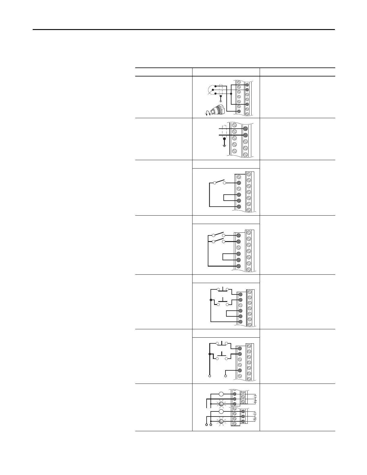
I/O Wiring Examples
This section shows examples of typical I/O wiring.
Input/Output Connection Example Required Parameter Settings
Potentiometer unipolar
speed reference
10k Ohm pot. recommended
(2k Ohm minimum)
Select speed reference source:
Param. 090 = 2 “Analog In 2”
Adjust Scaling:
Param. 091, 092, 322, 323
Check results:
Param. 017
Analog input unipolar speed
reference
0…+10V Input
Default speed reference source:
Param. 090 = 2 “Analog In 2”
Adjust Scaling:
Param. 091, 092, 325, 326
Check results:
Param. 017
Two-wire control
non-reversing
(1)
Internal supply Disable Digital Input 1:
Param. 361 = 0 “Not Used”
Set Digital Input 2:
Param. 362 = 7 “Run”
Two-wire control reversing
(1)
Internal supply Set Digital Input 1:
Param. 361 = 9 “Run Reverse”
Set Digital Input 2:
Param. 362 = 8 “Run Forward”
Three-wire control
(1)
Internal supply Use factory default parameter settings.
Digital Input 1:
Param. 361 = 4 “Stop – CF”
Digital Input 2:
Param. 362 = 5 “Start”
Three-wire control
(1)
External supply Use factory default parameter settings.
Digital Input 1:
Param. 361 = 4 “Stop – CF”
Digital Input 2:
Param. 362 = 5 “Start”
Digital output
Form C relays energized in normal
state
Select source:
Use factory default parameter settings.
Digital Out1 Sel:
Param. 380 = 1 “Fault”
Digital Out2 Sel:
Param. 384 = 4 “Run”
18
19
22
10
1
2
7
8
9
Run Fwd
Run Rev
+24V Common
1
2
8
Stop
Start
11
12
13
24
25
26
Power
Source
or

 Loading...


