38 Rockwell Automation Publication 20A-IN009E-EN-P - January 2015
PowerFlex 70 Adjustable Frequency AC Drive
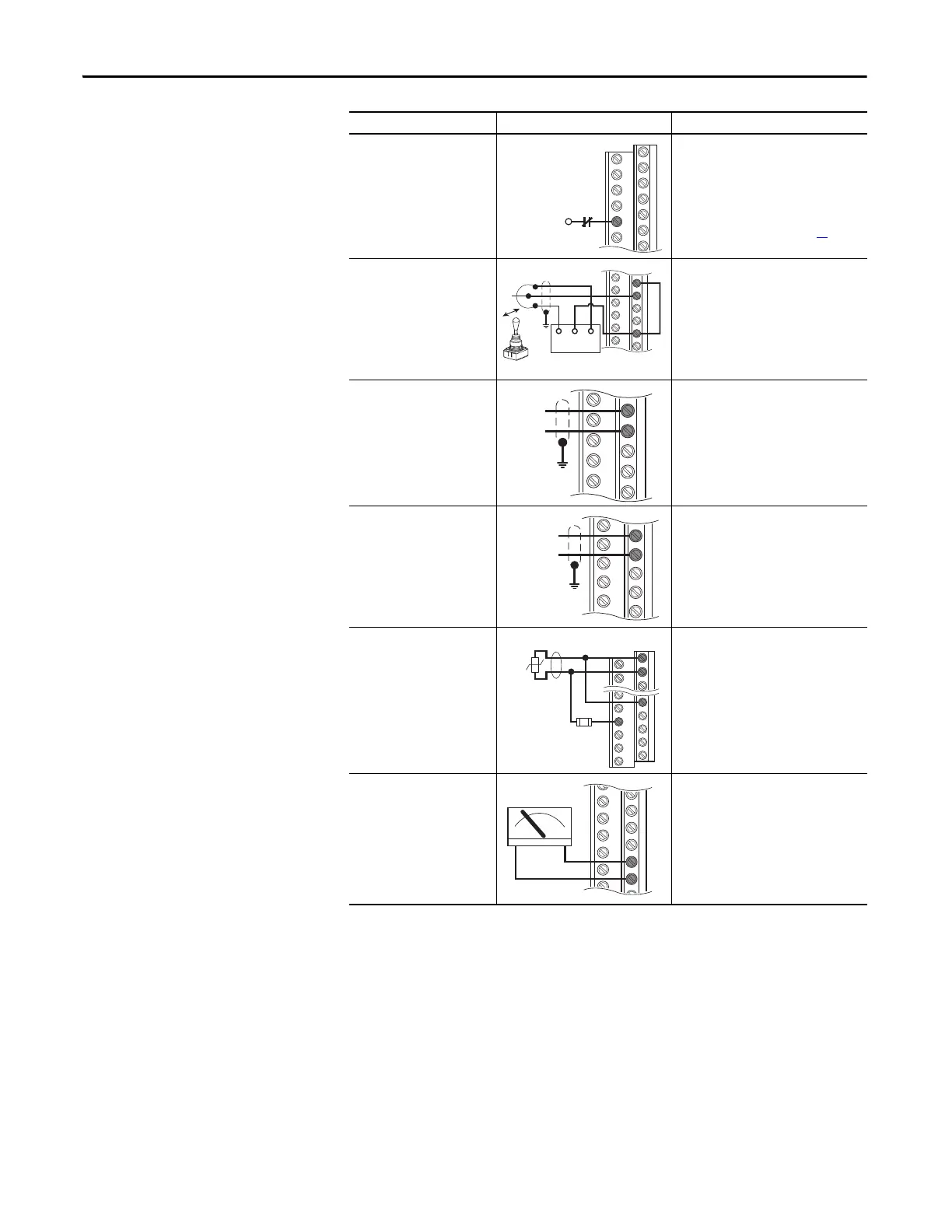
Enable input
Shown in enabled state.
Important: Digi
tal inputs are not
designed to work with a pulsed
source.
Standard control
Param. 366 = 1 “Enable”
Enhanced control
Param. 366 = 1 “Enable”
For dedicated hardware enable,
remove enable jumper (see page 39
)
Joystick bipolar speed
reference
±10V input
Set direction mode:
Param. 090 = 2 “Analog In 2”
Param. 190 = 1 “Bipolar”
Adjust scaling:
Param. 091, 092, 325, 326
Check results:
Param. 017
Analog input bipolar speed
reference
±10V input
Adjust scaling:
Param. 091, 092, 325, 326
Check results:
Param. 017
Analog input unipolar speed
reference
0…20 mA input
Configure input for current:
Param. 320, Bit #1 = 1 “Current”
Adjust scaling:
Param. 091, 092, 325, 326
Check results:
Param. 017
Analog input,
positive temperature
coefficient
PTC OT set > 5V
PTC OT cleared < 4V
PTC Short < 0.2V
Set Fault Config 1:
Param. 238, Bit #7 = 1 “Enabled”
Set Alarm Config 1:
Param. 259, Bit #11 = 1 “Enabled”
Analog output unipolar
0…+10V output.
Can drive a 2k Ohm load (25 mA
short circuit limit)
0…20 mA output.
400 Ohm max load.
Select source value:
Param. 342
Adjust scaling:
Param. 343, 344
(1) Digital inputs can be wired for 2-wire or 3-wire start/stop control. Three-wire control requires separate Start and Stop signals.
Two-wire control requires one input signal configured Run-Hi/Stop-Lo.
Input/Output Connection Example Required Parameter Settings
18
19
22
Com
Power Source
-10V +10V
18
19
–
+
14
15
22
10
3.32k
Ohm
1.8k
PTC
Ferrite
Bead
+–
22
23

 Loading...


