54 Rockwell Automation Publication 20A-IN009E-EN-P - January 2015
PowerFlex 70 Adjustable Frequency AC Drive
Table 25 - Drive Does Not Respond to Changes in Speed Command
Table 26 - Motor and/or Drive does Not Accelerate to Commanded Speed
Table 27 - Motor Operation is Unstable
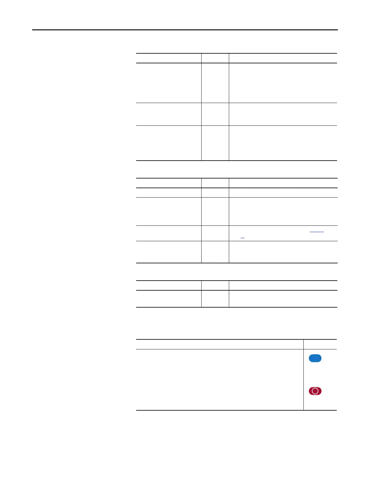
Manually Clearing Faults
Cause Indication Corrective Action
No value is coming from the source
of the command.
LCD HIM
Status Line
indicates “At
Speed” and
output is 0
Hz.
1. If the source is an analog input, check wiring and use a
meter to check for presence of signal.
2. Check [Commanded Freq] for correct source.
Incorrect reference source has been
programmed.
None 1. Check [Speed Ref Source] for the source of the speed
reference.
2. Reprogram [Speed Ref A Sel] for correct source.
Incorrect reference source is being
selected via remote device or digital
inputs.
None 1. Check [Drive Status 1], bits 12 and 13 for unexpected
source selections.
2. Check [Dig In Status] to see if inputs are selecting an
alternate source.
3. Reprogram digital inputs to correct “Speed Sel x” option.
Cause Indication Corrective Action
Acceleration time is excessive. None Reprogram [Accel Time x].
Excess load or short acceleration
times force the drive into current
limit, slowing or stopping
acceleration.
None Check [Drive Status 2], bit 10 to see if the drive is in Current
Limit.
Remove excess load or reprogram [Accel Time x].
Speed command source or value is
not as expected.
None Check for the proper Speed Command by using Table 25
on
page 54
.
Programming is preventing the
drive output from exceeding
limiting values.
None Check [Maximum Speed] and [Maximum Freq] to assure that
speed is not limited by programming.
Cause Indication Corrective Action
Motor data was incorrectly entered
or Autotune was not performed.
None 1. Correctly enter motor nameplate data.
2. Perform “Static” or “Rotate” Autotune procedure.
Step Key(s)
1. Press Esc to acknowledge the fault.
The fault information is removed so that you can use the Human Interface Module (HIM).
2. Address the condition that caused the fault.
The cause must be corrected before the fault can be cleared.
3. After corrective action has been taken, clear the fault by one of these methods:
• Press Stop.
• Cycle drive power.
• Set parameter 240 [Fault Clear] to “1”.
• “Clear Faults” on the Human Interface Module (HIM) Diagnostic menu.

 Loading...


