Rockwell Automation Publication 20A-IN009E-EN-P - January 2015 41
PowerFlex 70 Adjustable Frequency AC Drive
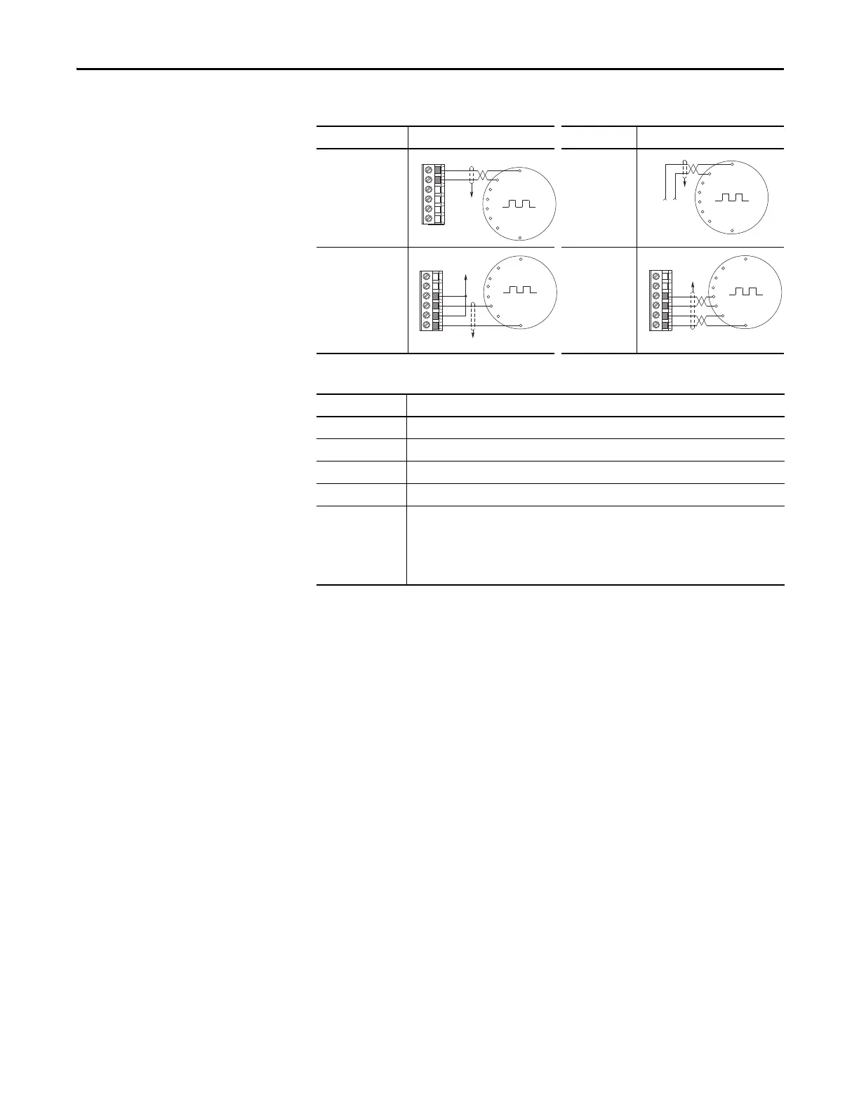
Figure 14 - Sample Encoder Wiring
Table 20 - Encoder Specifications
I/O Connection Example I/O Connection Example
Encoder power –
internal drive
power
Internal (drive) 12V
DC, 250 mA
Encoder power
–external
power source
Encoder signal –
single-ended,
dual channel
Encoder signal
–differential,
dual channel
Topic Description
Type Incremental, dual-channel
Supply 5V/12V Configurable ±5%
Quadrature 90° ±27°
Duty Cycle 50% +10%
Requirements Encoders must be line driver type, quadrature (dual channel) or pulse (single channel), single-
ended or differential and capable of supplying a minimum of 10 mA per channel. The encoder
interface board accepts 5V or 12V DC square-wave with a minimum high state voltage of 3.5V
DC (5V mode) and 7.0V DC (12V mode). Maximum low state voltage is 1V DC (for both 5V and
12V modes). Maximum input frequency is 250 kHz.
Common
+12V DC
(250 mA)
6
5
4
3
2
1
to SHLD
+
Common
External
Power
Supply
to
SHLD
A NOT
A
B
B NOT
to SHLD
to Power Supply
Common
6
5
4
3
2
1
to SHLD
6
5
4
3
2
1
A NOT
B
A
B NOT

 Loading...


