Chapter 3
Motor Control Center Vertical Sections
Features and Modifications
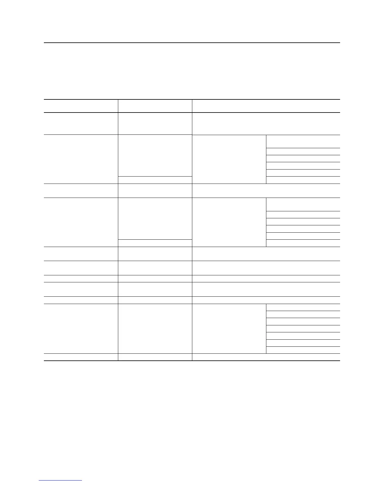
Table 3.A Motor Control Center Vertical Section Features and Modifications
1 All 1336 D and E-frame drive units and common DC bus F-frame drive units and PowerFlex frames 4 - 9 have 20" deep sections as standard. Common AC bus F-frame drive units and all
G-frame and H-frame drive units have 25"bump-back sections as standard.
2 If you are using a Bulletin 2364 front-end common-DC-bus supply unit in your lineup, verify that the front-end depth is compatible with the Bulletin 2362 sections that you are selecting.
3 If ANY one section is at least 20" deep, then ALL sections in that lineup must be at least 20" deep.
4 You must specify a power bus and a ground bus for each section.
5 3000A-rated horizontal power bus requires a 1/4" x 2" horizontal ground bus (PE) selection. Zero potential bus (TE) remains at 1/4" x 1" regardless of horizontal ground bus (PE) size selection.
Splice kits with 1/4" x 2" PE contain three 1/4" x 1" bus splices (Qty 2 for PE + Qty 1 for TE); splice kits with 1/4" x 1" PE contain two.
6 One kit required per shipping split on flush-front lineups. (Control bus splice kits are only required if lineup has control bus.)
7 Common AC bus F-frame drive units and all G-frame and H-frame drive units require base channels.
8 If you are using a Bulletin 2364 front-end unit in your lineup, lookup the base channel requirements of the front-end being utilized.
9 If ANY one section has base channels, then ALL sections in that lineup must have this optional base channel factory-installed. Base channels add 1.5" to the overall section height.
10 PowerFlex® frame 10 requires a 25” deep flush back section.
Section Features and
Modifications App. Notes Description
Section 1, 2, 3, 10 15” Deep
Depth 20” Deep
25” Deep (flush back)
Horizontal
Power Bus
4 Tin-plated copper busbar Bus
Rating
800A
1200A (AC only)
1600A
2000A
4, 5 3000A
Horizontal Power 42kAIC (rms Symmetrical)
Bus Bracing 65kAIC (rms Symmetrical)
Horizontal
Power Bus
Splice Kit
6 Splice bars and assembly
hardware.
Bus
Rating
800A
1200A
1600A
2000A
5, 6 3000A
Horizontal (PE / TE) 4, 5 1/4” x 1” PE and 1/4” x 1” TE tin-plated copper bus
Ground Bus 1/4” x 2” PE and 1/4” x 1” TE tin-plated copper bus
Horizontal Ground 5, 6 For 1/4” x 1” PE and 1/4” x 1” TE tin-plated copper bus
Bus Splice Kit For 1/4” x 2” PE and 1/4” x 1” TE tin-plated copper bus
Horizontal Control Bus Tin-plated copper 115V AC control bus rated at 90A
Horizontal Control Bus 6 For tin-plated copper 115V AC control bus rated at 90A
Splice Kit
Pull Box 12” High x 15” Deep, 20” Deep OR 25” Deep
Blank Unit Doors Covers unused unit space (includes
unit support pan)
0.5 SF
1.0 SF
1.5 SF
2.0 SF
2.5 SF
3.5 SF
4.5 SF
Base Channels 7, 8, 9 Two 1.5” x 3” mounting channels (One front, one rear)

 Loading...


