Rockwell Automation Publication 750-IN020D-EN-P - May 2017 21
PowerFlex 755 IP00, NEMA/UL Open Type Drive
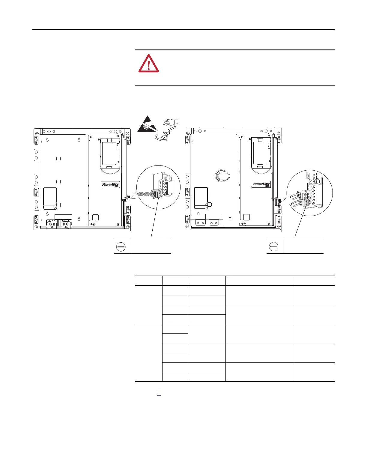
Figure 6 - Terminal Block for Enclosure Fans - TB2
TB2 Terminal Designations
ATTENTION: To avoid an electric shock hazard when servicing the drive, a
means for Lockout/Tagout of an external 120/240V power source must be
provided. Locking and tagging the common bus precharge disconnect switch
alone does not provide sufficient protection when servicing the drive.
Flat
0.5 N•m (4.5 lb•in)
Flat
0.5 N•m (4.5 lb•in)
=
AC Input Drive Common DC Input Drive
Drive Terminal Name Description Strip Length
AC Input
Drive
1 Shunt Trip Com. Do Not Use –
2 Shunt Trip N.O.
3 Fan 240V AC, 240 VA for enclosure fans 7.0 ±0.5 mm (0.28
±0.02 in.)
4Fan
Common DC
Input Drive
1 120V UPS Control
Power Input
Do Not Use –
2
3 120/240V Control
Power Input
Control Power (user supplied) - 120/
240V AC, 50/60 Hz, 8.3/4.2 A, 1 kVA
7.0 ±0.5 mm (0.28
±0.02 in.)
(1)
(1) See page 59 for control and I/O wire recommendations.
4
5 Fan 240V AC, 240 VA for enclosure fans 7.0 ±0.5 mm (0.28
±0.02 in.)
(2)
(2) See page 20 for wire recommendations.
6Fan
 Loading...


