Rockwell Automation Publication 750-QS001A-EN-P - March 2015 51
Reference Section
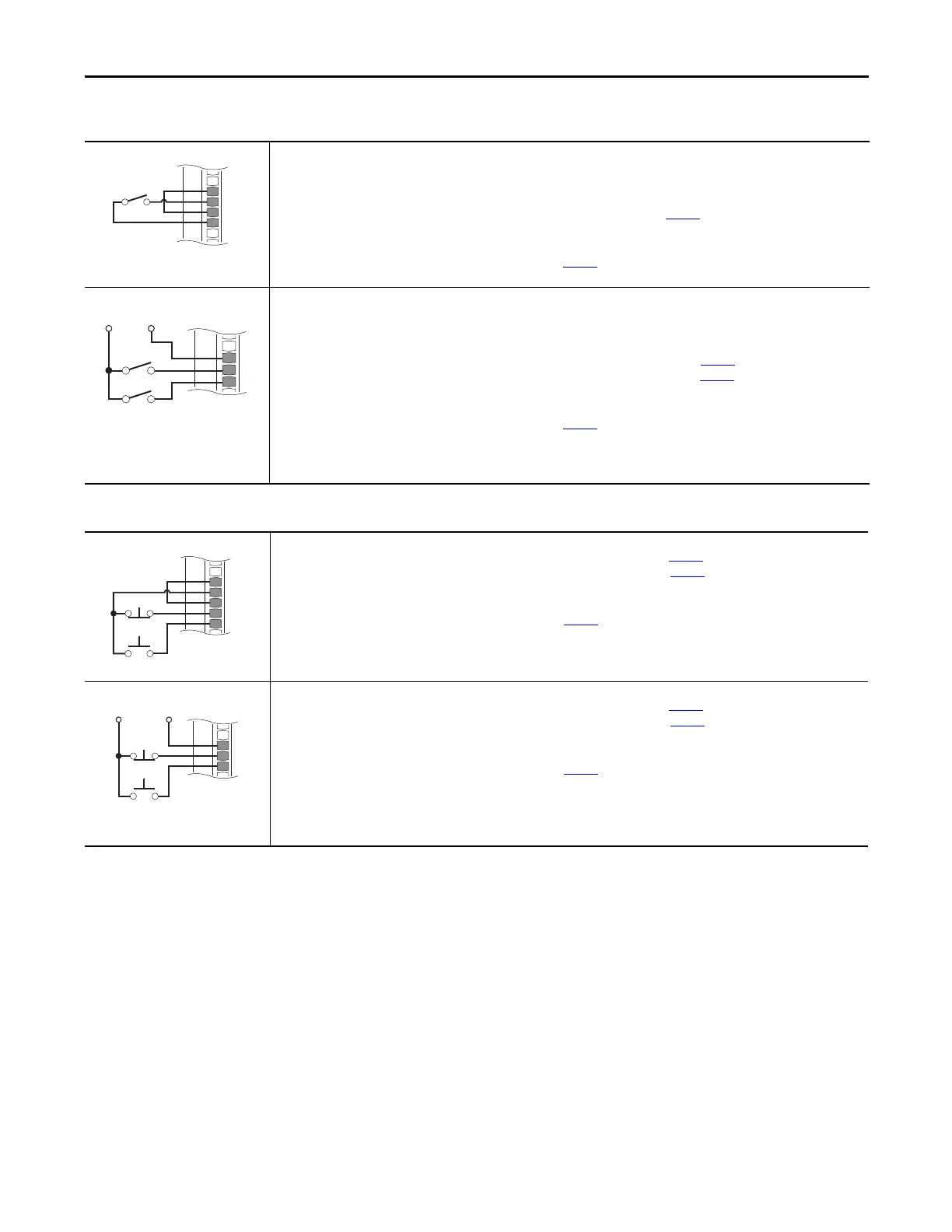
Table 33 - 2-Wire Control on 22-Series I/O Module
Non-Reversing - Internal Supply
22-Series I/O Module TB1
Set Direction Mode
Port 0: P308 [Direction Mode] = 2 “Rev Disable”
Set Selection
Port 0: P163 [DI Run] = Port 4 (or port where yo
ur 22-Series I/O Module is installed), See page 10: P1 [Dig In Sts], bit 0 = Input 0
View Results
Port 4 (or port where your 22-Series I/O Module is installed), See page
10: P1 [Dig In Sts]
Port 0: P935 [Drive Status 1]
Reversing - External Supply
22-Series I/O Module TB1
Set Direction Mode
Port 0: P308 [Direction Mode] = 0 “Unipolar”
Set Selection
Port 0: P164 [DI Run Forward] = Port 4 (or port where your 22-Series I/O Module is installed), See page 10: P1 [Dig In Sts], bit 0 = Input 0
Port 0: P165 [DI Run Reverse] = Port 4 (or port where
your 22-Series I/O Module is installed), See page 10: P1 [Dig In Sts], bit 1 = Input 1
View Results
Port 4 (or port where your 22-Series I/O Module is installed), See page 10: P1 [Dig In Sts]
Port 0: P935 [Drive Status 1]
IMPORTANT: Connect 24V supply only to 20-750-2262C-2R or 20-750-2263C-1R2T.
Table 34 - 3-Wire Control on 22-Series I/O Module
Internal Supply
22-Series I/O Module TB1
Set Selection
Port 0: P158 [DI Stop] = Port 4 (or port where your 22-Series I/O Module is installed), See page 10: P1 [Dig In Sts], bit 0 = Input 0
Port 0: P161 [DI Start] = Port 4 (or port where your 22-Series I/O Module is installed), See page
10: P1 [Dig In Sts], bit 1 = Input 1
View Results
Port 4 (or port where your 22-Series I/O Module is installed), See page 10: P1 [Dig In Sts]
Port 0: P935 [Drive Status 1]
External Supply
22-Series I/O Module TB1
Set Selection
Port 0: P158 [DI Stop] = Port 4 (or port where yo
ur 22-Series I/O Module is installed), See page 10: P1 [Dig In Sts], bit 0 = Input 0
Port 0: P161 [DI Start] = Port 4 (or port where your 22-Series I/O Module is installed), See page
10: P1 [Dig In Sts], bit 1 = Input 1
View Results
Port 4 (or port where your 22-Series I/O Module is installed), See page
10: P1 [Dig In Sts]
Port 0: P935 [Drive Status 1]
IMPORTANT: Connect 24V supply only to 20-750-2262C-2R or 20-750-2263C-1R2T.
C
onnect 120V supply only to 20-750-2262D-2R.

 Loading...


