Rockwell Automation Publication 750-PC108A-EN-P - April 2021 39
PowerFlex 755T Drives Configured to Order Program Product Information
Braided Busbar to Drive Output Busbar Connection Hardware
To determine if you must make a connection using this hardware during installation, see Electrical Connections Made to Each Configured Bay During Installation on page 17. This hardware is used to make the power
connection from the drive power bay to some types of configured output bay.
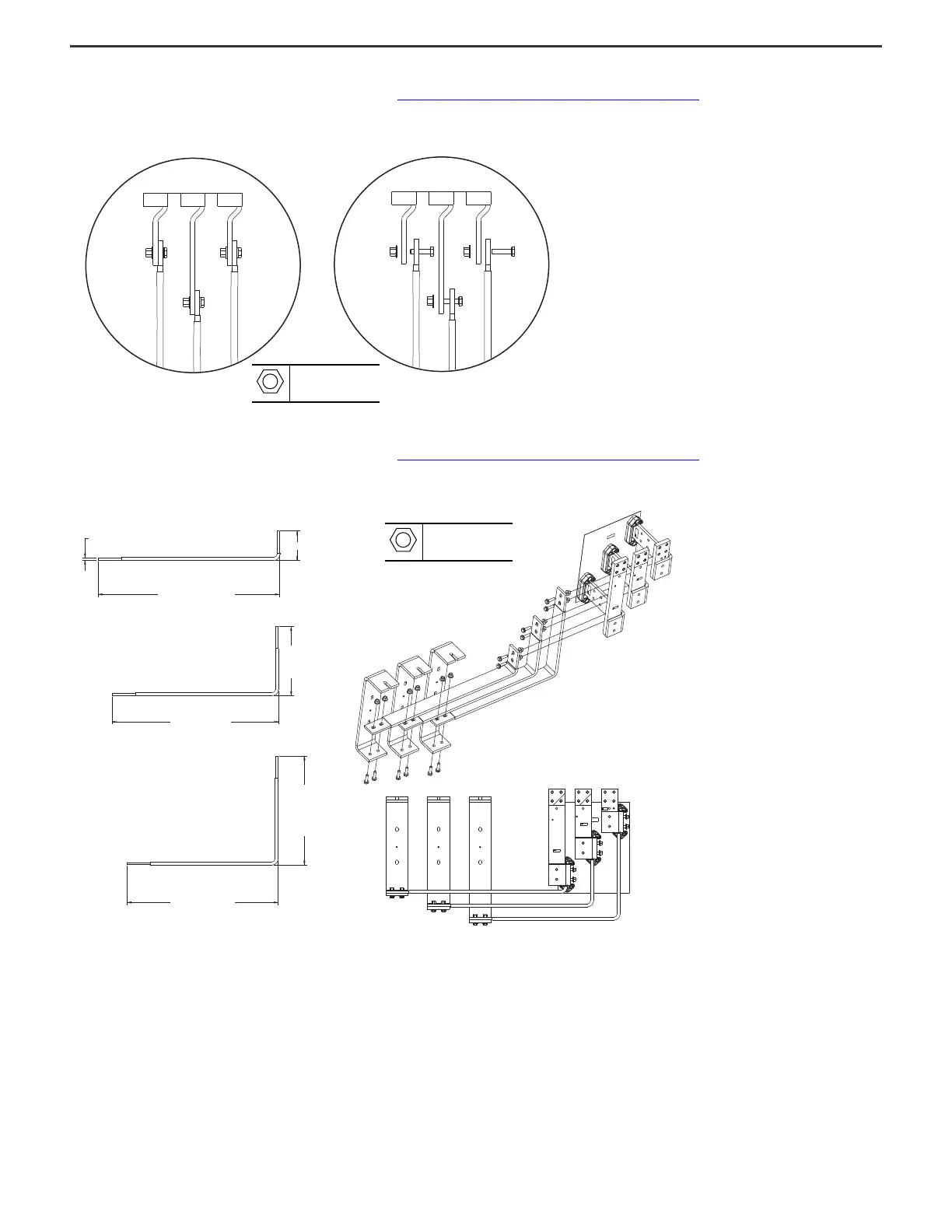
Figure 38 - Braided Busbar Connections to Drive Output Busbars
Flexibar Flexible Busbar Connection Hardware
To determine if you must make a connection using this hardware during installation, see Electrical Connections Made to Each Configured Bay During Installation on page 17. This hardware is used to make the power
connection from some types of configured input bay to the drive input bay.
Figure 39 - Flexibar Connection Hardware (dimensions in mm [in.])
M10
40 mm
57 N•m (504 lb•in)
685.6
[26.99]
495.31
[19.50]
754.6
[29.71]
314.5
[12.38]
821.6
[32.35]
133.7
[5.26]
10
[0.39]
M10
40 mm
100 N•m (885 lb•in)

 Loading...


