6 Rockwell Automation Publication 750-PC108A-EN-P - April 2021
PowerFlex 755T Drives Configured to Order Program Product Information
Catalog Number Explanation
Your product has a catalog number that contains codes that identify characteristics of the product. The catalog number is on the product data nameplates. There is a data nameplate on the outside of the door of each
configured input bay, and another data nameplate on the top protective touch guard of each configured input bay or control panel. For an explanation of your catalog number, see the PowerFlex 755T Drives Configured to
Order Program Installation Instructions, publication 750-IN118
.
Installation Location
When choosing the installation location for your product, make sure that the location meets the following requirements:
• Allows the product to be installed in a vertical orientation as shown in the drawings.
• Provides a flat and level mounting surface, allowing the product to make full contact with the mounting surface and stay stable.
• Allows the bays to be square, and not deformed in any way.
• Provides a mounting surface that can support the weight of the product. See Shipment Sections and Approximate Weights
on page 11.
• Does not expose the product to dust or metallic particles.
• Does not expose the product to a corrosive atmosphere.
• Does not expose the product to moisture and direct sunlight.
• Does not expose the product to environmental conditions that are inconsistent with the Environmental Specifications
on page 5.
• Provides sufficient space for the product given its dimensions, required clearances, and access requirements. These topics are covered in the following sections: Approximate Dimensions
,
Overhead Clearance
on page 8, Airflow Clearances and Considerations on page 8, and Service Cart Access Requirements on page 10.
Also consider the following when choosing the installation location for your product:
• Ventilation and air conditioning concerns beyond just meeting the ambient temperature requirements
• Input power cable entry points
• Motor cable exit points
• Alignment with other equipment
• Future needs
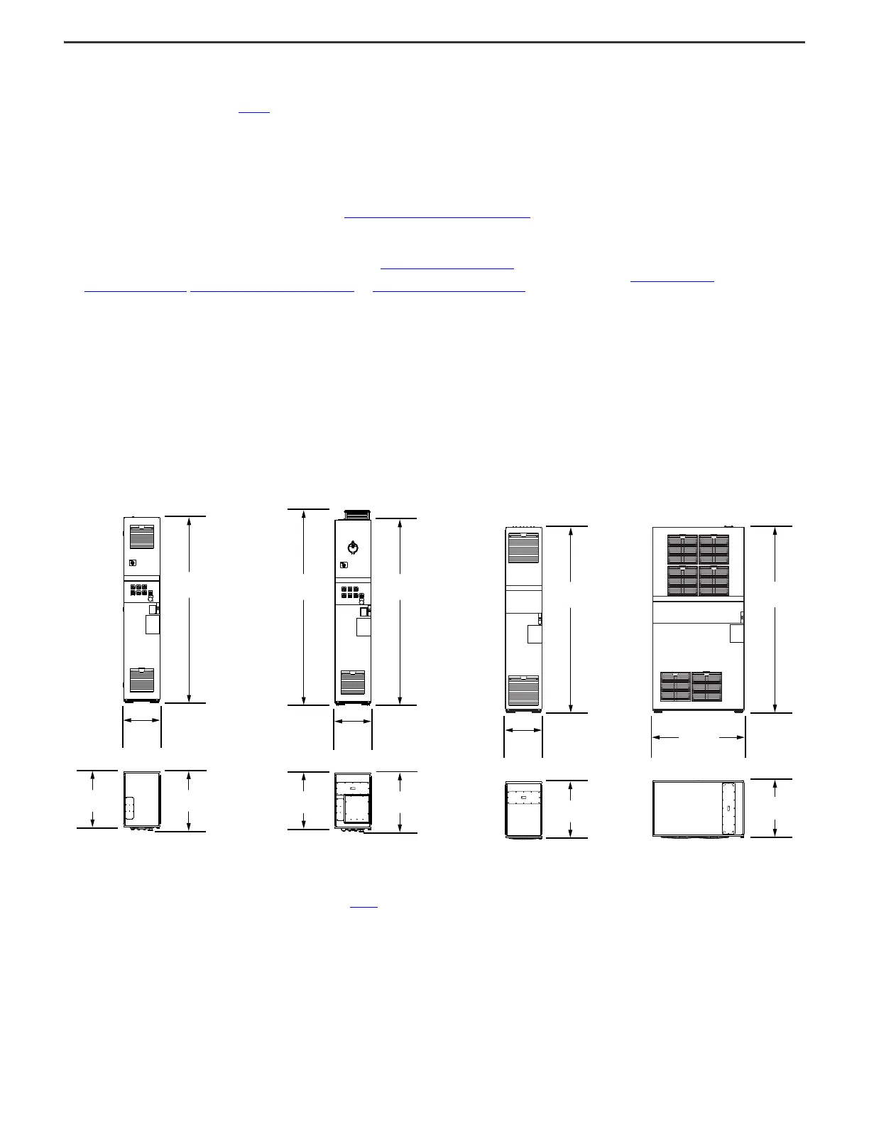
Approximate Dimensions
This section provides the approximate dimensions of the configured input bays and configured output bays. A front view and top view are shown for each bay or category of bays.
Frame 8
Figure 1 - Frame 8 Configured Input Bay with
Control-only (No Input Protection)
Figure 2 - Frame 8 Configured Input Bays with Input
Protection
The approximate dimensions for Frame 8 configured
input bays with input protection apply to the
following bays:
• Configured input bay with fuses, top entry (bay
that is shown in Figure 2
)
• Configured input bay with fuses, bottom entry
• Configured input bay with circuit breaker, top
or bottom entry
Figure 3 - Frame 8 Configured
Output Bay with Contactor Only,
Top or Bottom Exit
Figure 4 - Frame 8 Configured Output Bay with
Sine-wave Filter and Contactor, Top or Bottom
Exit
2017.0 mm
(79.41 in.)
401.0 mm
(15.79 in.)
647.2 mm
(25.48 in.)
605.9 mm
(23.85 in.)
2017.0 mm
(79.41 in.)
2118.3 mm
(83.40 in.)
401.0 mm
(15.79 in.)
647.2 mm
(25.48 in.)
605.9 mm
(23.85 in.)
2021.0 mm
(79.57 in.)
401.0 mm
(15.79 in.)
605.9 mm
(23.85 in.)
2017.0 mm
(79.41 in.)
1000.4 mm
(39.39 in.)
605.0 mm
(23.82 in.)

 Loading...


