Rockwell Automation Publication 750-PC108A-EN-P - April 2021 27
PowerFlex 755T Drives Configured to Order Program Product Information
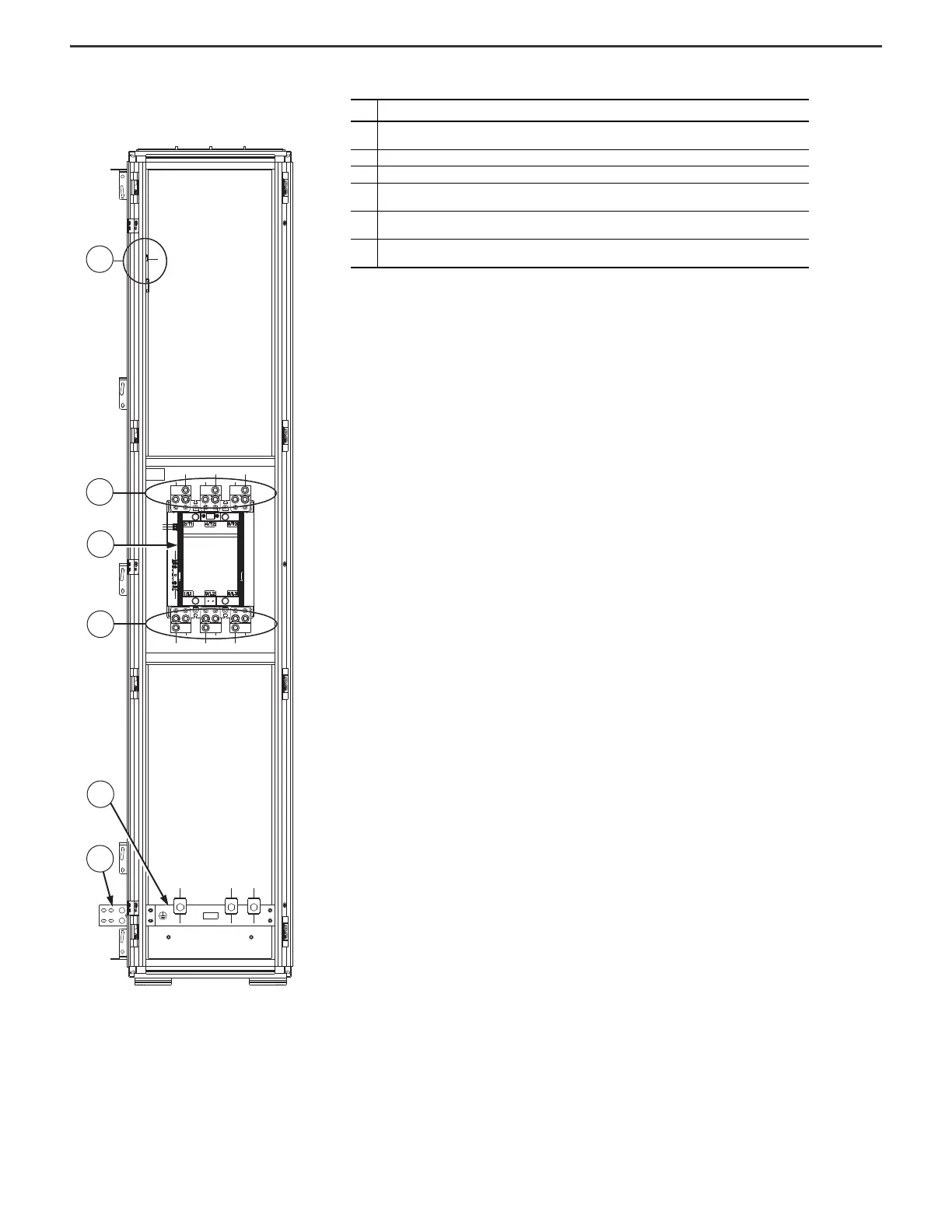
Figure 23 - Frame 8 Configured Output Bay with Output Contactor Only,
Top or Bottom Exit: Internal Components and Installation Connection
Locations
Item Description
1
Configured bay control connectors for control connection to configured input bay (not visible in this view, located
behind bay frame). Connections must be made during installation. In this area, there is also a thermostat.
2 Terminal lugs for power to customer motor. Connections must be made during installation.
3Contactor
4
Terminal lugs for power from the drive. Connections are made on the contactor at the factory. Connections must be
made to the drive during installation.
5
PE ground bar with ground clamps included. Terminating point to chassis ground for motor and motor cable shield.
Ground connections must be made during installation.
6
PE ground bar splice connection hardware. Ground splice connection to drive PE ground bar must be made during
installation.

 Loading...


